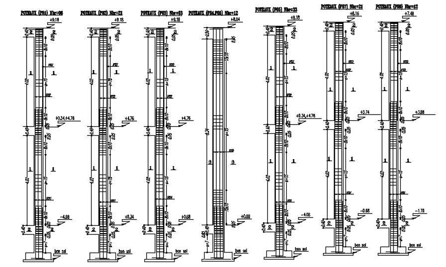
2d Design Of Different Sizes Of Columns With Reinforcement Details In

Different Sizes Of Column Sections With Reinforcement Details Desig 5.6.4 example 5.4 – design and detailing of a steel reinforced concrete column with rectilinear transverse reinforcement not designated as part of the sfrs in a building assigned to sdc d 5 68 5.6.5 example 5.5 – design and detailing of a steel reinforced concrete column with. Columns are any more slender members which carry primarily axial compressive loads. columns always require reinforcing aci 318 19 section 10.6.1. minimum reinforcing to insure ductile failure: 1% i.e. as ag ≥ 0.01. maximum reinforcing to prevent blockage: 8% i.e. as ag ≥ 0.08 in practice 4% is better.

2d Design Of Different Sections Of Column With Reinforcement Detail The structural design of reinforced concrete (r.c.) columns involves the provision of adequate compression reinforcement and member size to guaranty the stability of the structure. in typical cases, columns are usually rectangular, square, or circular in shape. other sections such as elliptical, octagonal, etc are also possible. By laurin ernst updated april 6, 2024. reinforced concrete columns resist vertical loads that act on a building such as wind, snow, dead and live load. the columns then transfer these loads to the foundations. in this guide, we’ll show step by step, how you design reinforced concrete columns according to en 1992 1 1. 5.3 detailing the longitudinal reinforcement. 5.3.1 minimum number of longitudinal bars. 5.3.2 spacing of longitudinal bars. 5.3.3 splices of longitudinal reinforcement. 5.4 design and detailing the transverse reinforcement. 5.4.1 overview. chapter 5. determining and detailing the required reinforcement. 5 1. Figure 4 16 shows an interaction diagram for a reinforced concrete column. this diagram gives the combinations of axial load and moment required to cause failure of a column cross section or. very short length of column. the dashed radial line o a is a plot of the end moment on the column in figure 4 15.

Different Sizes Of Wall And Column Sections With Reinforcement Details 5.3 detailing the longitudinal reinforcement. 5.3.1 minimum number of longitudinal bars. 5.3.2 spacing of longitudinal bars. 5.3.3 splices of longitudinal reinforcement. 5.4 design and detailing the transverse reinforcement. 5.4.1 overview. chapter 5. determining and detailing the required reinforcement. 5 1. Figure 4 16 shows an interaction diagram for a reinforced concrete column. this diagram gives the combinations of axial load and moment required to cause failure of a column cross section or. very short length of column. the dashed radial line o a is a plot of the end moment on the column in figure 4 15. 1.1 background. the two main parameters governing column design are: bracing: if the column can sway additional moments are generated through the. p − δ effect. this does not affect braced columns. slenderness ratio: the effective length divided by the lateral dimension of the column. Columns are defined as members that carry loads in compression. usually they carry bending moments as well, about one or both axes of the cross section. the bending action may produce tensile forces over a part of the cross section. despite of the tensile forces or stresses that may be produced, columns are. axial compression.

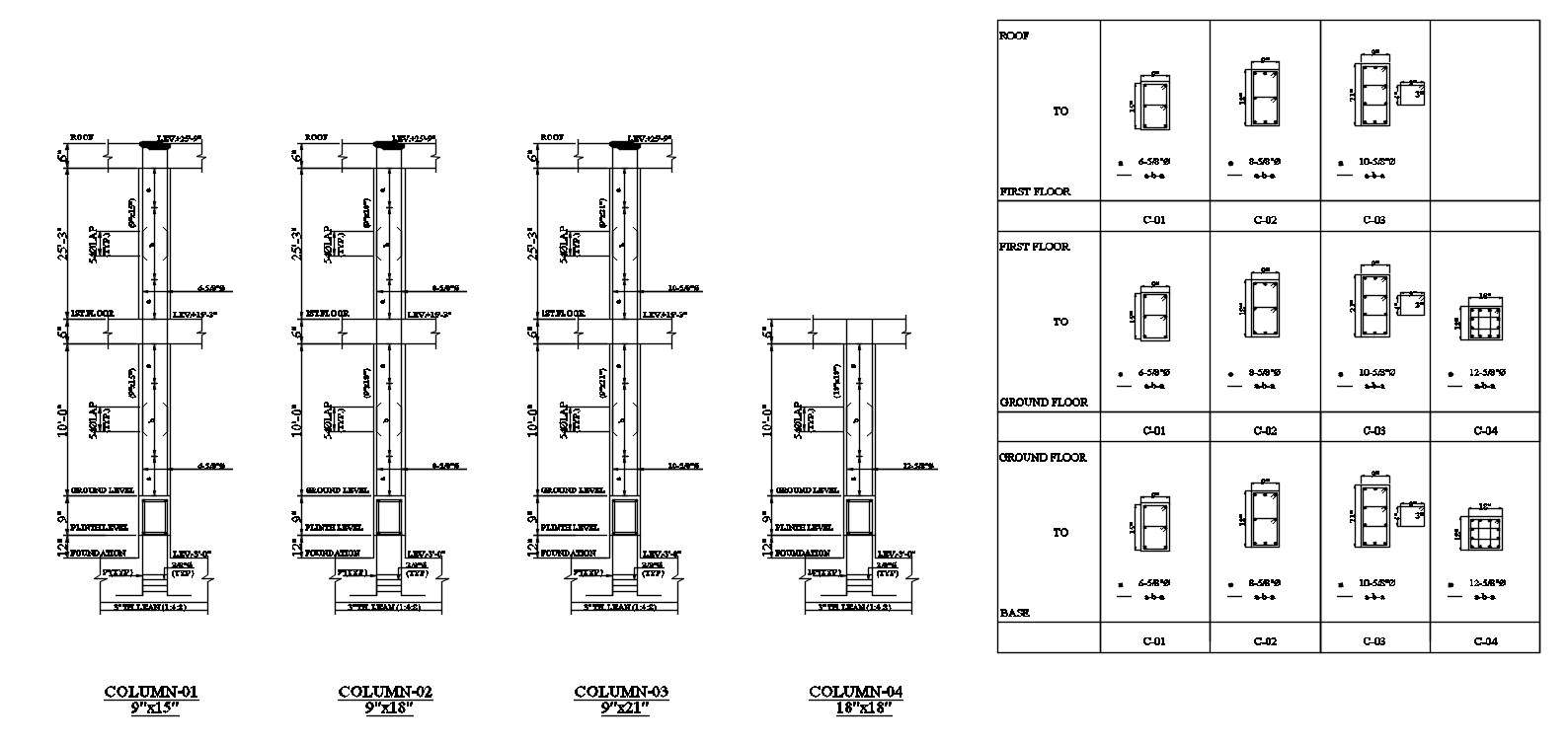
Column Reinforcement Details Of The Different Floors In Autocad 2d 1.1 background. the two main parameters governing column design are: bracing: if the column can sway additional moments are generated through the. p − δ effect. this does not affect braced columns. slenderness ratio: the effective length divided by the lateral dimension of the column. Columns are defined as members that carry loads in compression. usually they carry bending moments as well, about one or both axes of the cross section. the bending action may produce tensile forces over a part of the cross section. despite of the tensile forces or stresses that may be produced, columns are. axial compression.

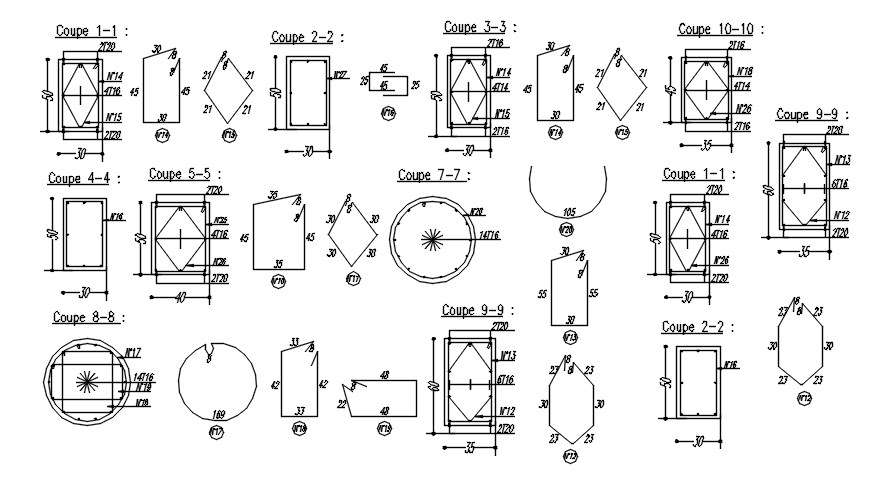
Cross Sections 1 To 9 Of Different Shapes Of Columns With Reinforcement

Comments are closed.