3 Phase Brake Wiring

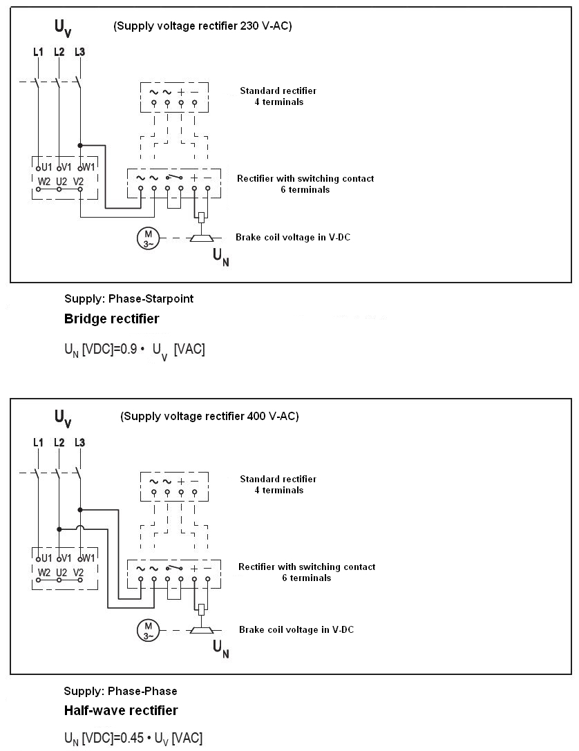
3 Phase Brake Wiring Bg or bge brake rectifier. motor wired for high voltage. brake voltage matches high motor voltage. example: 220 380v motor motor wired 380v brake voltage 380v. the bg brake rectifier standard for frame sizes up to 100, not available on frame sizes above 100. the brake rectifier bg is a half wave rectifier with overvoltage protection. A wiring diagram is the best way to ensure this. wiring diagrams for 3 phase electric motor brakes typically include a schematic diagram to illustrate the different components of the circuit. this includes the power supply, the motor, and the various switches and sensors used to control the motor. it also includes the connections between the.

How To Wire 480v 3 Phase Brake Motor Wiring Flow Line Overall, the 3 phase motor brake is an essential component for controlling the movement of a 3 phase motor in industrial applications. it ensures the safety and precision of the motor’s operation, allowing for efficient and reliable performance. step by step guide to wiring a 3 phase motor brake. Elektrim brake service manual 3 the brake disk (11) has two friction linings situated between the mounting disk (9) and the armature (5). in brakes envisaged for direct mounting onto the motor bearing shield, the role of the mounting disk is performed by the motor bearing shield. acting on the armature (5) is the force of. Wiring a three phase motor is an essential step in industrial and commercial electrical installations. three phase motors are commonly used in various applications, such as pumps, fans, compressors, and more. these motors provide a higher power output compared to their single phase counterparts, making them ideal for heavy duty operations. It is typically a three phase induction motor, which offers high efficiency and reliability. the motor is connected to the power supply through appropriate wiring connections. the brake: the electromagnetic brake in an ac brake motor is activated when the power to the motor is turned off. it consists of an electromagnetic coil and a friction disc.

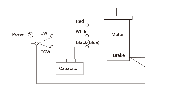
3 Phase Brake Motor Wiring Diagram Wiring a three phase motor is an essential step in industrial and commercial electrical installations. three phase motors are commonly used in various applications, such as pumps, fans, compressors, and more. these motors provide a higher power output compared to their single phase counterparts, making them ideal for heavy duty operations. It is typically a three phase induction motor, which offers high efficiency and reliability. the motor is connected to the power supply through appropriate wiring connections. the brake: the electromagnetic brake in an ac brake motor is activated when the power to the motor is turned off. it consists of an electromagnetic coil and a friction disc. The three main components of a 3 phase wiring diagram for motors are: power supply: the diagram shows the three phase power supply, typically labeled as l1, l2, and l3. these represent the three separate phases of the power source. motor: the diagram illustrates the motor as a single unit with labeled terminals. 3. brake motors & brake gearmotors must be securely & adequately grounded. this can be accomplished by wiring with a grounded metal clad raceway system, by using a separate ground wire connected to the bare metal of the motor frame, or other suitable means. refer to nec article 250 (grounding) for additional information. all wiring.

3 Phase Electric Motor Brake Wiring Diagram Webmotor Org The three main components of a 3 phase wiring diagram for motors are: power supply: the diagram shows the three phase power supply, typically labeled as l1, l2, and l3. these represent the three separate phases of the power source. motor: the diagram illustrates the motor as a single unit with labeled terminals. 3. brake motors & brake gearmotors must be securely & adequately grounded. this can be accomplished by wiring with a grounded metal clad raceway system, by using a separate ground wire connected to the bare metal of the motor frame, or other suitable means. refer to nec article 250 (grounding) for additional information. all wiring.

Comments are closed.