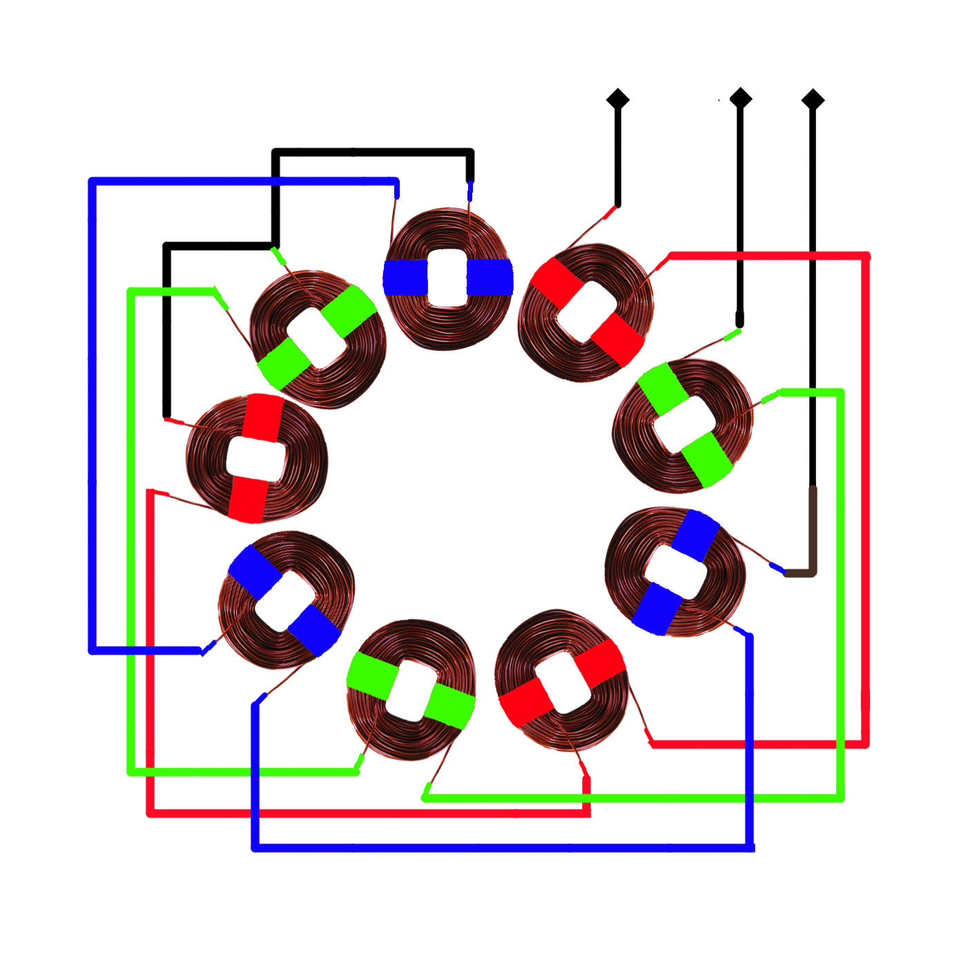
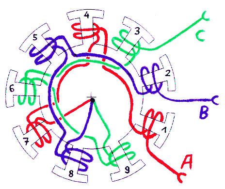
3 Phase Stator Diagram Wiring Schematic

3 Phase Stator Visualisation Hugh Piggott S Blog The diagram of a 3 phase stator winding is a visual representation that shows the arrangement of the coils in a 3 phase induction motor. it is an essential tool for understanding the electrical connections and phases involved in the motor’s operation. the stator winding diagram typically consists of three sets of coils symmetrically spaced. The 3 wire stator diagram shows the three winding coils of the stator, each connected to a separate wire. these wires are commonly labeled as phases, and are denoted as phase a, phase b, and phase c. the three phase system is widely used in power generation and distribution due to its efficiency and ability to handle large amounts of electrical.

3 Phase Stator Diagram Wiring Schematic The 3 wire stator wiring diagram typically includes three main wires: phase a, phase b, and phase c. these wires are responsible for conducting the three phases of ac power generated by the stator. understanding the proper connection of these wires is essential for ensuring the correct functioning of the electrical system. This diagram illustrates the electrical connections between the stator windings of a motor, which are responsible for generating the rotating magnetic field necessary for motor operation. a 3 phase motor typically consists of three sets of windings, known as phases, labeled as a, b, and c. these windings are evenly distributed around the stator. The most common type of three phase motor is that which has nine labeled (and often colored) wires coming out of the box on the side. there are many motors with more or fewer wires, but nine is the most common. these nine wire motors may be internally connected with either a wye (star) or a delta configuration, established by the manufacturer. In this tutorial, we will demonstrate the automatic star delta (y Δ) starting method for 3 phase ac induction motors. this will include providing a schematic, power and control, plc ladder, and wiring diagrams. we will also explain how the star delta starter works and discuss its applications, as well as its advantages and disadvantages.

Comments are closed.