4 3 Coolant Flow Diagram

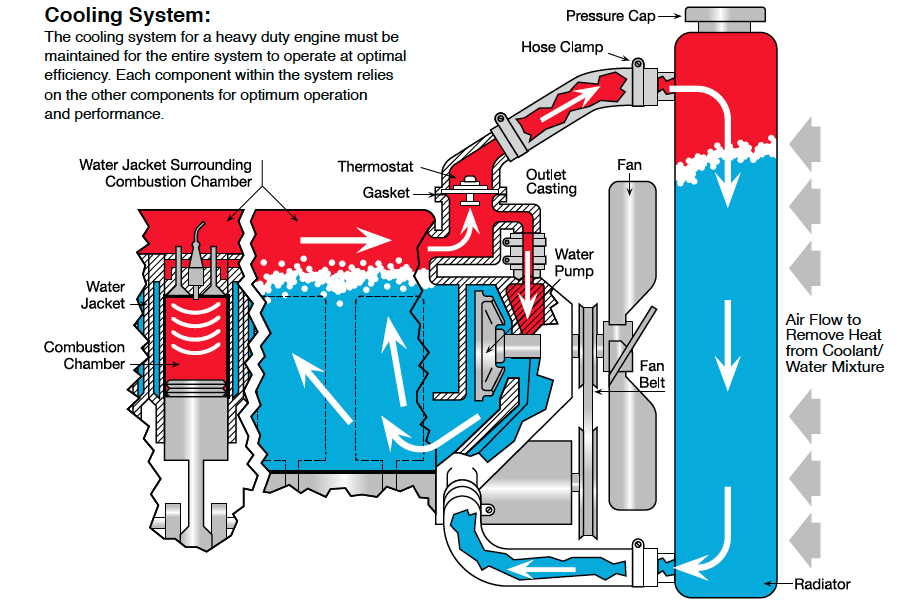
4 3 Coolant Flow Diagram Although my 4.3 was running at about 195 degrees (that's with a stock spec thermostat) and seemed pretty stable, i decided to flush the cooling system because the coolant looked rusty. after the flush, i refilled it with a50 50 mix of antifreeze and water. now it runs hotter on the highway. the upper radiator hose is the highest point in the. Coolant starts at the lower radiator hose and goes into the water pump. wp has dual outlets and splits in two, one of each side to both sides of the block. enters the block at the bottom and travels evenly throughout the block. comes out the block at the top around each cylinder. there are small holes in the head gasket that restricts the flow.

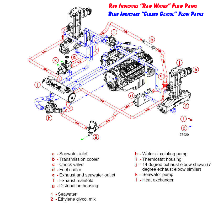
4 3 Coolant Flow Diagram The ls engine coolant flow diagram is an essential part of understanding how the cooling system in an ls engine works. this diagram shows the path that coolant takes through the engine, from the radiator to the water pump and back again. understanding this flow is crucial for diagnosing any cooling system problems and ensuring that the engine. Oct 19, 2010. #2. re: 4.3 mpi cooling diagram. on my 4.3 there is a hose that runs from the transom to the thermostat housing. just track it from the transom down by the outdrive. it's true that on a back fill you should see pink running out of the leg onto your driveway. i usually take this hose off and blow through the hose at the thermostat. 3. thermostat. the thermostat is a temperature controlled valve that controls the flow of the coolant to the radiator. when the engine is cold, the thermostat is closed. this way the coolant stays inside the engine and helps it to get warmed up quicker. once the coolant is warmed up from the engine, it needs to be cooled down. The water pump contains a centrifugal impeller, which spins rapidly and creates a suction force that draws coolant into the pump’s inlet port. these blades push the coolant through the pump’s outlet hose and into the engine block. the impeller blades are engineered in a way to create a steady flow of coolant, even at low speeds.

Schematic 4 3 Mercruiser Engine Diagram 3. thermostat. the thermostat is a temperature controlled valve that controls the flow of the coolant to the radiator. when the engine is cold, the thermostat is closed. this way the coolant stays inside the engine and helps it to get warmed up quicker. once the coolant is warmed up from the engine, it needs to be cooled down. The water pump contains a centrifugal impeller, which spins rapidly and creates a suction force that draws coolant into the pump’s inlet port. these blades push the coolant through the pump’s outlet hose and into the engine block. the impeller blades are engineered in a way to create a steady flow of coolant, even at low speeds. A coolant system diagram is a visual representation of the components and flow path of a cooling system in an engine. the cooling system plays a crucial role in maintaining the temperature of an engine and preventing overheating. it circulates a liquid coolant through the engine, absorbs heat from the various components, and dissipates it into. Components of the chevy 350 cooling system. these are the components of the chevy 350 coolant flow diagram: water pump: the water pump is driven by the engine’s crankshaft and is responsible for circulating the coolant throughout the engine. it draws coolant from the radiator and pushes it into the engine block.

Comments are closed.