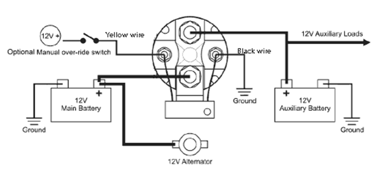
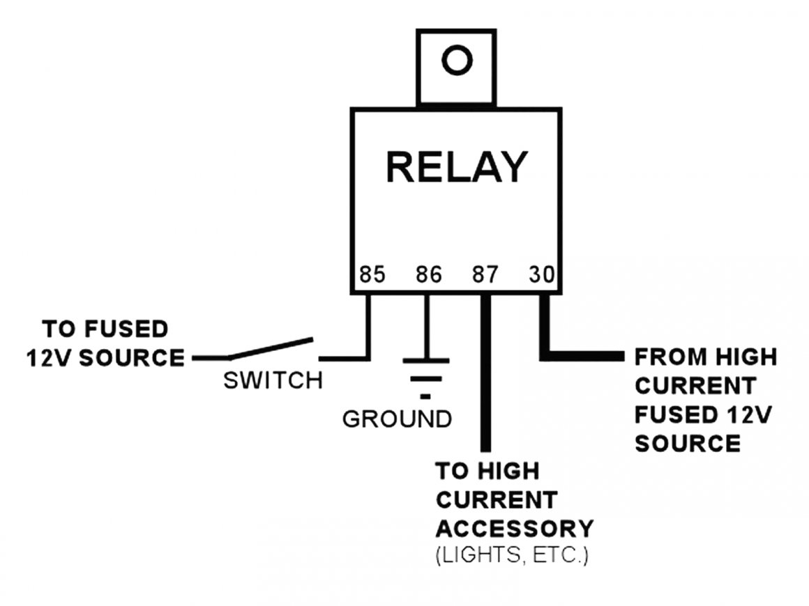
4 Pole Solenoid Wiring Diagram

4 Pole Solenoid Wiring Diagram How It Works Circuits Gallery Learn how to wire a 4 pole solenoid, an electromagnetic device that controls the flow of electrical current or fluids in a system. follow the step by step guide to connect the coil windings, power supply, and control switches or relays. Wiring diagram of 4 pole solenoid. a starting solenoid typically has four terminals: two for the high current circuit and the other two for the low current terminals, which are connected to the inner coil and activate the high current device on the high power end. the connectors are 2 tiny solenoid switch connections.

Gain A Better Understanding Of 4 Pole Solenoid Wiring Diagrams вђ Moo Learn how to connect a 4 pole solenoid switch to activate and deactivate high current circuits in your car. see a simple schematic, a video tutorial and tips on choosing the right wires and terminals. Step 2: identify the solenoid terminals. next, identify the terminals on the 4 post starter solenoid. there are typically four terminals labeled “batt”, “s”, “r”, and “m”. the “batt” terminal connects to the positive terminal of the battery, while the “s” terminal connects to the ignition switch. the “r” terminal. We're back with another helpful automotive wiring diagram video. in this video, we'll be taking a close look at ford 4 pole starter solenoid wiring diagrams . A 4 pole solenoid wiring diagram for a lawn mower provides a visual representation of how the solenoid should be connected to the battery, starter motor, ignition switch, and other components. the wiring diagram typically includes four terminals on the solenoid, labeled as follows: battery positive ( ), starter positive ( ), ignition switch.

Understanding The 4 Pole Solenoid Wiring Diagram A Step By Step Guide We're back with another helpful automotive wiring diagram video. in this video, we'll be taking a close look at ford 4 pole starter solenoid wiring diagrams . A 4 pole solenoid wiring diagram for a lawn mower provides a visual representation of how the solenoid should be connected to the battery, starter motor, ignition switch, and other components. the wiring diagram typically includes four terminals on the solenoid, labeled as follows: battery positive ( ), starter positive ( ), ignition switch. Here’s a quick recap of the key points: the starter solenoid is essentially a high current relay activated by your ignition switch to turn the starter motor. 4 pole solenoids have dedicated terminals for coil power, ignition, battery, and switch connections. correct wiring diagrams are essential references during diagnosis and repair. This article will provide a step by step guide to wire a 4 pole continuous duty solenoid. the first step is to identify the four terminals of the solenoid. these are usually labeled "l1," "l2," "r1," and "r2." the terminals labeled "l1" and "l2" are the power inputs, while the terminals labeled "r1" and "r2" are the outputs.

4 Pole Starter Solenoid Wiring Diagram Lawn Mower Here’s a quick recap of the key points: the starter solenoid is essentially a high current relay activated by your ignition switch to turn the starter motor. 4 pole solenoids have dedicated terminals for coil power, ignition, battery, and switch connections. correct wiring diagrams are essential references during diagnosis and repair. This article will provide a step by step guide to wire a 4 pole continuous duty solenoid. the first step is to identify the four terminals of the solenoid. these are usually labeled "l1," "l2," "r1," and "r2." the terminals labeled "l1" and "l2" are the power inputs, while the terminals labeled "r1" and "r2" are the outputs.

Comments are closed.