Air Conditioner Wiring Diagram Troubleshooting

Ac Wiring Diagram Troubleshooting Wiring Digital And Schematic The diagram typically includes information about the power supply, thermostat, compressor, fan motor, condenser, and evaporator. it shows how these components are connected and how the electrical current flows through the system. an air conditioner wiring diagram is an essential tool for anyone working on or installing an air conditioning system. Here is a basic air conditioner wiring diagram for the power supply: l1 and l2: these are the terminals for the supply voltage from the electrical panel. l1 is the hot wire, and l2 is the neutral wire. fuse or circuit breaker: this component is used to protect the circuit from overloading.

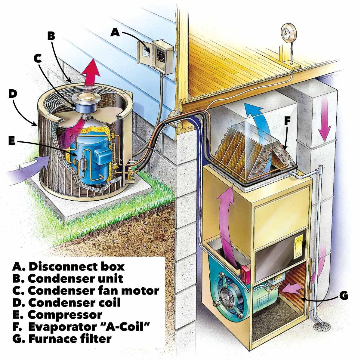
Ac Repair How To Troubleshoot And Fix An Air Conditioner Diy Project When troubleshooting hvac wiring diagrams, it is important to have a thorough understanding of the system’s electrical components and their interconnections. these diagrams provide a visual representation of the electrical circuits and connections within the hvac system, including the power supply, control components, and sensors. Basic steps for wiring an air conditioner. run electrical cable from the service panel to an air conditioner disconnect switch near the a c unit and connect it to a new circuit breaker in the panel. turn the breaker off. prepare a length of cable to run from the disconnect switch to the a c unit’s control panel. R or rc wire (power) connected to the r power terminal to power the thermostat. w wire (heat), connected to the heating control. g wire (fan) connected to the fan control to operate a blower in your hvac system. y1 wire (cooling) connected to the y terminal compressor refrigerant system. An air conditioning unit wiring diagram is a schematic representation of the electrical connections and components of an air conditioning system. it shows how different wires and components are connected to each other, allowing for a visual understanding of the system’s electrical layout. in a basic wiring diagram for an air conditioning unit.

Comments are closed.