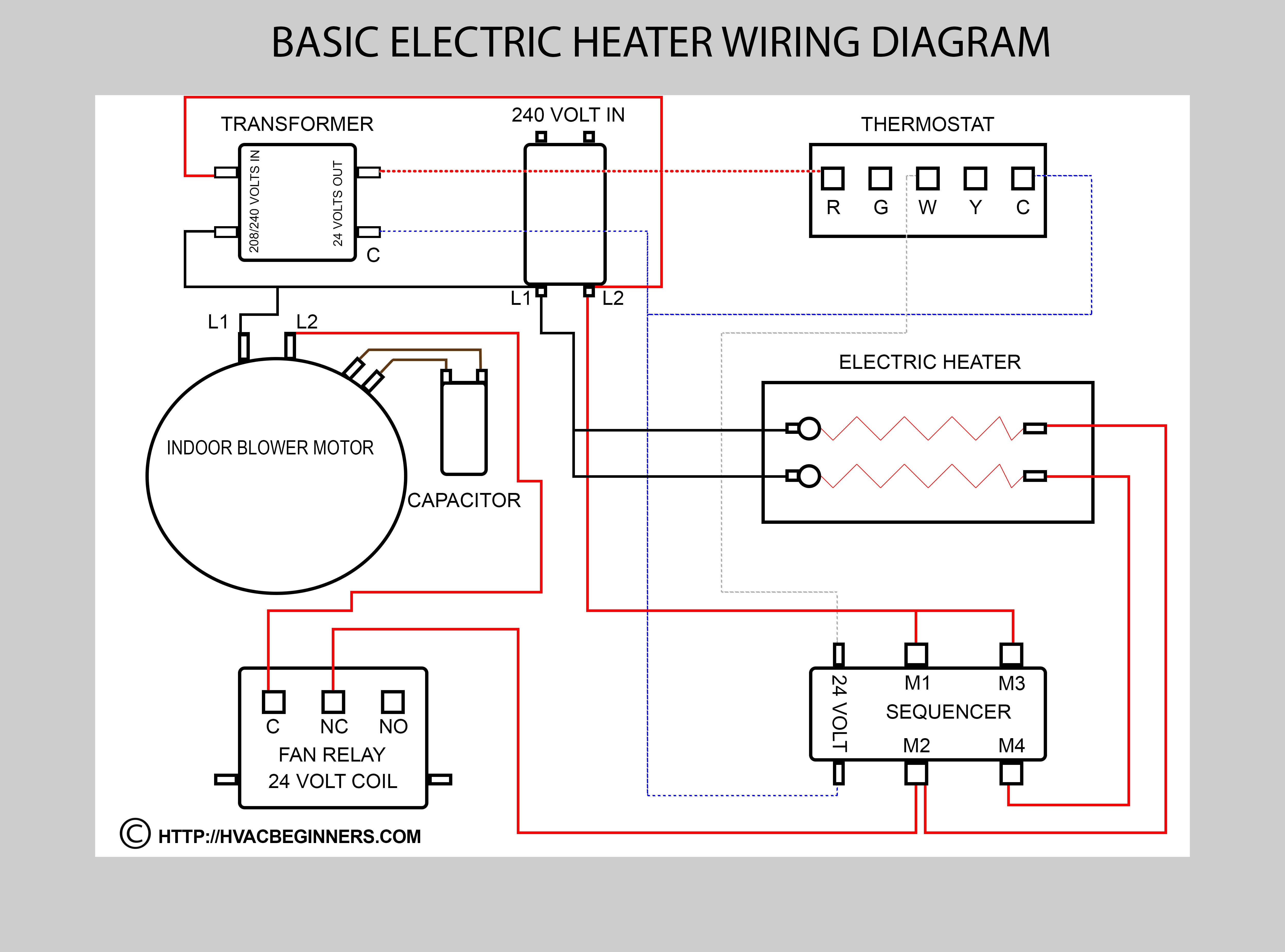
Basic Hvac Electric Wiring

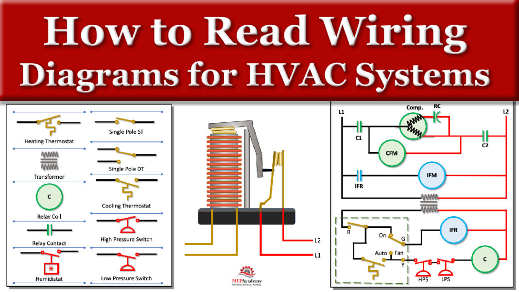
How To Read Wiring Diagrams In Hvac Systems Mep Academy R or rc wire (power) connected to the r power terminal to power the thermostat. w wire (heat), connected to the heating control. g wire (fan) connected to the fan control to operate a blower in your hvac system. y1 wire (cooling) connected to the y terminal compressor refrigerant system. Wiring diagrams are essentially blueprints that depict the electrical connections and functions of the various components in an hvac system. they include details such as the locations of switches, transformers, motors, capacitors, and relays, as well as how these components are wired together. by studying these diagrams, technicians can.

How To Read Wiring Diagrams In Hvac Systems Mep Academy Basics of hvac wiring. in order to understand how an hvac system works, it’s important to have a basic understanding of hvac wiring. hvac wiring refers to the electrical connections between various components of an hvac system, including the thermostat, air conditioner, furnace, and heat pump. proper wiring is crucial for the system to. In the field of heating, ventilation, and air conditioning (hvac), wiring diagrams play a crucial role in understanding and troubleshooting the electrical systems. these diagrams provide a visual representation of the wiring connections and components involved in the hvac system. by understanding the basics of hvac wiring diagrams, technicians. Loads usually sit at the end of a circuit; after power moves from the power supply through an inline switch or switches, the load or loads are powered up and begin functioning. loads include motors, compressors, contactors, relay coils, and light bulbs. loads perform work and draw amperage. this basic wiring diagram includes all three main. Connecting all of the electrical components together is the electric wiring. to keep track of wiring, hvac technicians rely on circuit schematics or visual representations of wiring programs. there are three basic types of circuit schematics used in hvac today. they are the line diagram, the ladder diagram, and the installation diagram.

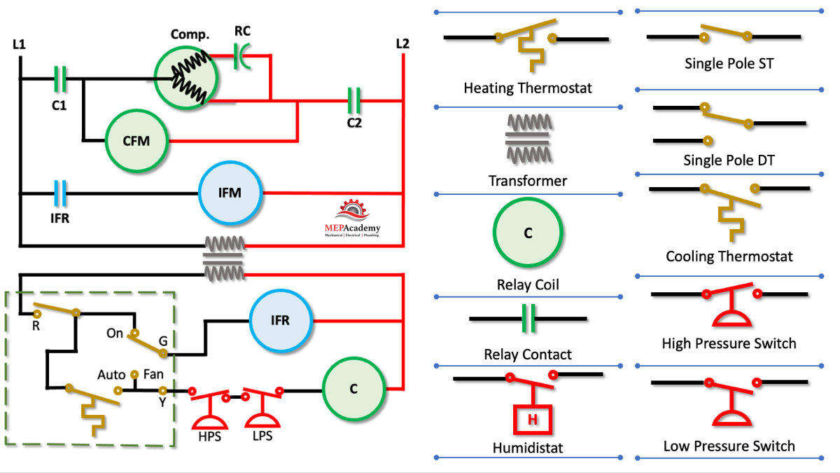
Hvac Wiring Explained Loads usually sit at the end of a circuit; after power moves from the power supply through an inline switch or switches, the load or loads are powered up and begin functioning. loads include motors, compressors, contactors, relay coils, and light bulbs. loads perform work and draw amperage. this basic wiring diagram includes all three main. Connecting all of the electrical components together is the electric wiring. to keep track of wiring, hvac technicians rely on circuit schematics or visual representations of wiring programs. there are three basic types of circuit schematics used in hvac today. they are the line diagram, the ladder diagram, and the installation diagram. In this hvac training video, i show how to use an hvac electrical training board to teach electrical wiring, components, wiring diagrams, and electrical trou. Hvac wiring diagram and legend. we’ll jump right into showing you a schematic diagram for a simple air conditioning unit. we’ll make a ladder diagram using a simple air conditioner as our example. first we have the main electrical supply lines l1 and l2 providing 208 230 volt, single phase power. then we’ll need a transformer to provide.

Basic Hvac Electric Wiring In this hvac training video, i show how to use an hvac electrical training board to teach electrical wiring, components, wiring diagrams, and electrical trou. Hvac wiring diagram and legend. we’ll jump right into showing you a schematic diagram for a simple air conditioning unit. we’ll make a ladder diagram using a simple air conditioner as our example. first we have the main electrical supply lines l1 and l2 providing 208 230 volt, single phase power. then we’ll need a transformer to provide.

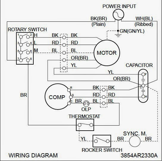
Electrical Wiring Diagrams For Air Conditioning Systems вђ Part One

Comments are closed.