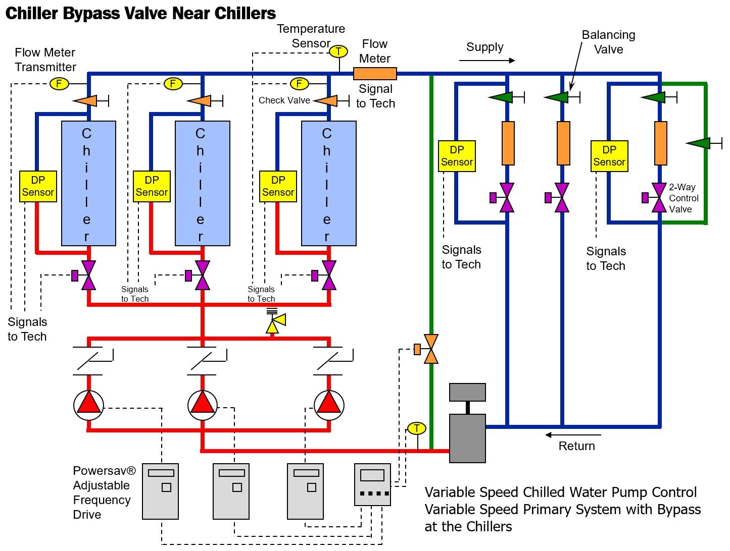
Chilled Water System Schematic Diagram

Schematic Of A Typical Chilled Water System Download Scientific Diagramођ Chilled water schematic and condenser water schematic, how to read and understand the engineering drawings with real world examples, illustrations, animations and video tutorial. covering chillers, pump sets, ahus, risers, primary and secondary systems, cooling towers and bypass lines. A chiller is made up of the 4 major components required for the refrigeration process which are: a) compressor, b) condenser, c) evaporator and d) expansion valve. to produce chilled water, the refrigerant absorbs heat from the water and thus, chilling the water to about 6.7°c (44°f).

Variable Primary Chilled Water Systems Part 3 The Basics Of Variable The chilled water schematic diagram is a visual representation of the components and flow of a chilled water system. it provides an overview of how the system works and allows engineers and technicians to understand how the different parts of the system are connected and interact with each other. the schematic diagram typically starts with a. Comprehensive chilled water system design. system catalog. 2 chilled water systems provide customers with flexibility for meeting first cost and efficiency objectives, while centralizing maintenance and complying with or exceeding energy code minimum requirements. a comprehensive approach to system design can minimize the power draw of the. The schematic diagram of a chilled water system typically includes the following key components: chiller: the chiller is the heart of the system and is responsible for generating chilled water. it cools the water to a specific temperature using a refrigeration cycle. The designed performance of a chilled water system is 1.5 mw at a design Δt of 6°c. if the system is suffering from low Δt syndrome, the cooling capacity will be reduced dramatically. if the real Δt is only 2°c, the system’s cooling capacity is reduced with two thirds. the performance of the system is now only 0.5 mw.

Comments are closed.