Chilled Water System Schematic Diagram Pdf

Chilled Water System Schematic Diagram Pdf Chilled water schematic and condenser water schematic, how to read and understand the engineering drawings with real world examples, illustrations, animations and video tutorial. covering chillers, pump sets, ahus, risers, primary and secondary systems, cooling towers and bypass lines. Comprehensive chilled water system design. system catalog. 2 chilled water systems provide customers with flexibility for meeting first cost and efficiency objectives, while centralizing maintenance and complying with or exceeding energy code minimum requirements. a comprehensive approach to system design can minimize the power draw of the.

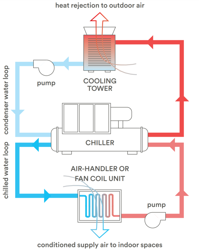
Schematic Of A Typical Chilled Water System Download Scientific Diagramођ Leaving chilled water temperature rises, so do the refrigerant temperature and pressure. when the l eaving chilled water temper ature changes, the work a compressor must do also changes. the effect of leaving chilled water temperature change on power consumption can be 1.0 to 2.2 percent per degree fahrenheit [1.8 to 4.0 percent per degree. Solve at load, mitigate at plant. if csd chillers – run chillers to max load (supply temp rise). do not run more chillers than needed (water cooled, single compressor assumed) if vsd chillers – run chillers between 30% and 80% load (depending on ecwt and actual off design performance curves). run more chillers than load requires. The designed performance of a chilled water system is 1.5 mw at a design Δt of 6°c. if the system is suffering from low Δt syndrome, the cooling capacity will be reduced dramatically. if the real Δt is only 2°c, the system’s cooling capacity is reduced with two thirds. the performance of the system is now only 0.5 mw. The chilled water schematic diagram is a visual representation of the components and flow of a chilled water system. it provides an overview of how the system works and allows engineers and technicians to understand how the different parts of the system are connected and interact with each other. the schematic diagram typically starts with a.

How A Chilled Water System Works Hvac Training Shop The designed performance of a chilled water system is 1.5 mw at a design Δt of 6°c. if the system is suffering from low Δt syndrome, the cooling capacity will be reduced dramatically. if the real Δt is only 2°c, the system’s cooling capacity is reduced with two thirds. the performance of the system is now only 0.5 mw. The chilled water schematic diagram is a visual representation of the components and flow of a chilled water system. it provides an overview of how the system works and allows engineers and technicians to understand how the different parts of the system are connected and interact with each other. the schematic diagram typically starts with a. A chilled water piping schematic is a detailed diagram that shows the flow of chilled water through the system. it includes information about pipe sizes, valve locations, pump configurations, and other important components. this schematic is typically used by engineers, contractors, and hvac technicians to understand how the system is designed. This course provides a description of common chilled water system types from the most basic constant flow to all variable flow systems along with advantages and limitations. for purposes of discussion, chilled water pumping systems are divided into three categories. 1. constant volume chilled water systems 2. primary secondary chilled water.

Comments are closed.