Control Wiring 3 Wire Control Start Stop Circuit вђ Tw Contro

Control Wiring 3 Wire Control Start Stop Circuit вђ The 3 wire start stop control circuit is the most common electrical diagram that you will need to understand. you will see it used anytime that we want to r. #accesstopower #motorcontrol #accesselectric accesstopower in this video, i demonstrate a 3 wire start stop circuit with multiple push buttons. thi.

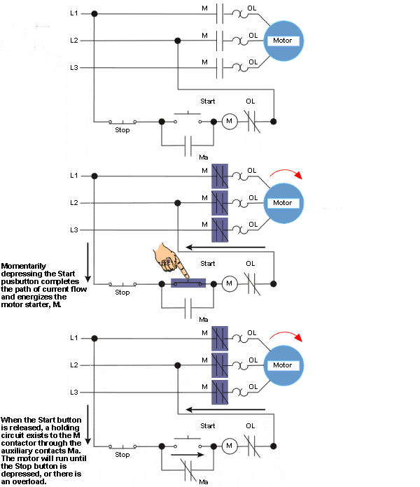
Control Wiring 3 Wire Control Start Stop Circuit вђ #accesstopower #motorcontrol, accesstopower in this video, i demonstrate a 3 wire start stop circuit. i describe each of the components involved, s. Figure 2: wire diagram for the 3 wire start stop circuit developed using kicad. returning to figure 2, observe that the motor starter components are depicted in three places. the coil, labeled m1, is near the center of the diagram, the overload block is on the right, and the normally open auxiliary contact is in parallel with the start pushbutton. Figure 1. three wire control of a 3 phase ac motor with a 3 pole electromagnetic motor starter. the two series pb switches in the 3 wire control of a 3 phase ac motor (figure 1) replace the single selector switch contacts in the 2 wire control of the 3 phase ac motor. the no start pb switch serves to initiate (start or turn on) a control function. Start stop circuit with start button pressed. when we press the start button it allows current to flow through the circuit and activate the relay or contactor coil. an example of where a contactor would be used is when controlling a motor. when the coil of the contactor is activated it allows current to flow to the motor, this will run the motor.
Start Stop Circuits A Brief Introduction Into Its Components Working Figure 1. three wire control of a 3 phase ac motor with a 3 pole electromagnetic motor starter. the two series pb switches in the 3 wire control of a 3 phase ac motor (figure 1) replace the single selector switch contacts in the 2 wire control of the 3 phase ac motor. the no start pb switch serves to initiate (start or turn on) a control function. Start stop circuit with start button pressed. when we press the start button it allows current to flow through the circuit and activate the relay or contactor coil. an example of where a contactor would be used is when controlling a motor. when the coil of the contactor is activated it allows current to flow to the motor, this will run the motor. When creating a ladder diagram for a 3 wire control circuit, several key elements need to be considered. power supply: the first step in creating a ladder diagram is to determine the power supply for the circuit. this can be a voltage source such as a power supply or a battery. control devices: the next step is to identify the control devices. Here are some guidelines to consider: 1. use clearly labeled wires: labeling the wires in your motor control circuit can greatly simplify troubleshooting and maintenance. use clear and descriptive labels for each wire, such as “power supply,” “start button,” “stop button,” “motor,” etc. 2. use color coded wires:.

How To Wire A Start Stop Motor Control 3 Wire Circuit Yout When creating a ladder diagram for a 3 wire control circuit, several key elements need to be considered. power supply: the first step in creating a ladder diagram is to determine the power supply for the circuit. this can be a voltage source such as a power supply or a battery. control devices: the next step is to identify the control devices. Here are some guidelines to consider: 1. use clearly labeled wires: labeling the wires in your motor control circuit can greatly simplify troubleshooting and maintenance. use clear and descriptive labels for each wire, such as “power supply,” “start button,” “stop button,” “motor,” etc. 2. use color coded wires:.

Understanding The Basics Of Start Stop Circuits

Comments are closed.