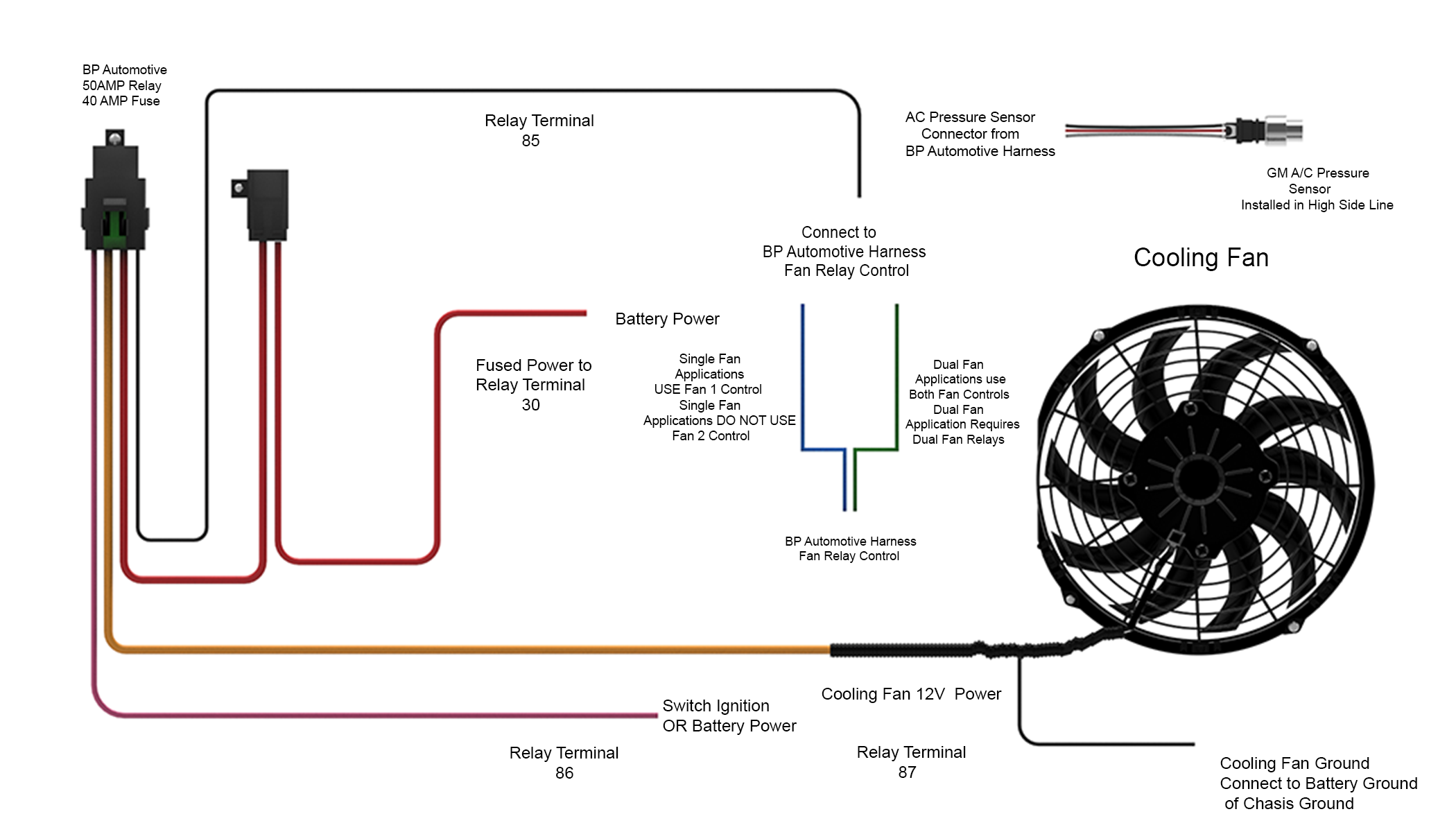
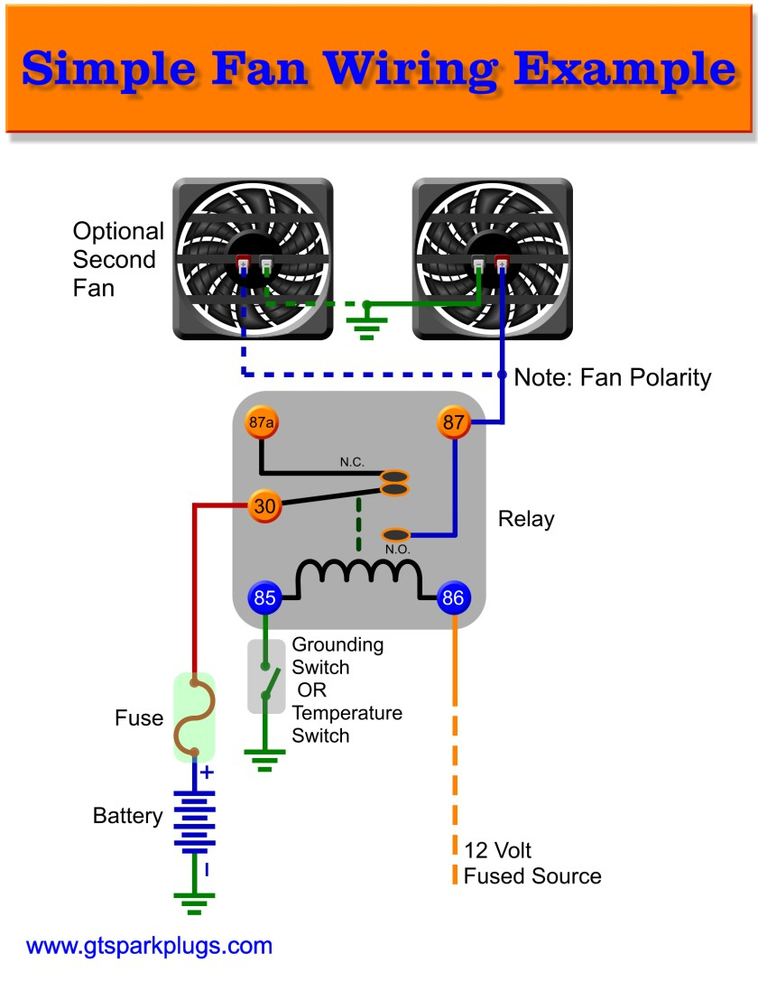
Cooling System Wiring Diagram

Electric Cooling Fan Wiring Diagram R or rc wire (power) connected to the r power terminal to power the thermostat. w wire (heat), connected to the heating control. g wire (fan) connected to the fan control to operate a blower in your hvac system. y1 wire (cooling) connected to the y terminal compressor refrigerant system. Here’s how to wire a thermostat using the color code and, fyi, each terminal’s purpose. attach the red wire to the r terminal (call for heating and or cooling). attach the green wire to the g terminal (fan). attach the white wire to the w terminal (heat). attach the yellow wire to the y terminal (ac).

Wiring Diagram Electric Cooling Fan In hvac wiring diagrams, the symbol for the power supply represents the electrical source that provides the necessary energy to operate the heating, ventilation, and air conditioning system. this symbol typically consists of a straight line with a small circle at the end, indicating the connection point to the power source. Hvac wiring diagram and legend. we’ll jump right into showing you a schematic diagram for a simple air conditioning unit. we’ll make a ladder diagram using a simple air conditioner as our example. first we have the main electrical supply lines l1 and l2 providing 208 230 volt, single phase power. then we’ll need a transformer to provide. Consult your owners install guide for wiring examples and systems compatible with your thermostat*. the thermostat uses one wire to control the primary functions of your hvac system, such as heating, cooling, and fan. see the diagram below for the role of each wire in your system: s – indoor and outdoor wired sensors. Product wiring diagram wiring diagram description pdf download. home; our products. kwikool portable cooling systems. 10404 mula rd. stafford, texas 77477. 713.

Electric Cooling Fan Control Wiring Diagram Consult your owners install guide for wiring examples and systems compatible with your thermostat*. the thermostat uses one wire to control the primary functions of your hvac system, such as heating, cooling, and fan. see the diagram below for the role of each wire in your system: s – indoor and outdoor wired sensors. Product wiring diagram wiring diagram description pdf download. home; our products. kwikool portable cooling systems. 10404 mula rd. stafford, texas 77477. 713. Overview of different heat pump terminals. as shown in the diagram, you will need to power up the thermostat, and the 24v ac power is connected to the r and c terminals. the color of wire r is usually red wire, and c is black wire. the c wire is known as the common wire. these two connections will ensure that there is power to the thermostat. This system provides an advanced cooling solution with its innovative features and easy installation process. the system is designed to work seamlessly with your existing wiring, making it a convenient and hassle free upgrade for your vehicle. the vintage air gen iv system comes with a comprehensive wiring diagram that provides step by step.

How To Wire Auto Electric Cooling Fan Overview of different heat pump terminals. as shown in the diagram, you will need to power up the thermostat, and the 24v ac power is connected to the r and c terminals. the color of wire r is usually red wire, and c is black wire. the c wire is known as the common wire. these two connections will ensure that there is power to the thermostat. This system provides an advanced cooling solution with its innovative features and easy installation process. the system is designed to work seamlessly with your existing wiring, making it a convenient and hassle free upgrade for your vehicle. the vintage air gen iv system comes with a comprehensive wiring diagram that provides step by step.
Engine Cooling Fan Wiring Diagram Circuit Diagram

Comments are closed.