Cooling Tower Fan Power Calculation At Jeanne Pugh Blog

Cooling Tower Fan Power Calculation At Jeanne Pugh Blog This calculation is for a cooling tower with constant speed fans. measured input data include spot measurements for true power and motor operational time per hour, as measured by motor on off loggers on each fan in the tower. convert seconds on per hour to average energy per hour (worksheet: “step 2. energy calcs”). Hi there, i'm involved a project where i must determine the power requirements of a forced draft cooling tower that uses a large fan. unfortunately i'm pretty new at cooling towers and i'm having several issues with this: issue 1 i've read a lot of material on cooling towers at this point where i came across this: fan horsepower = a*(cfm.

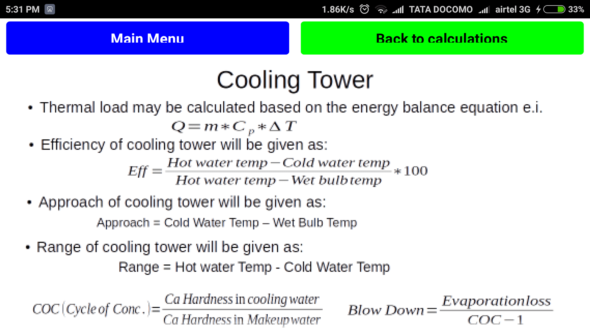
Cooling Tower Fan Power Calculation At Jeanne Pugh Blog Method 1. evaporation rate = (flow) x (range) x 0.001. the evaporation rate can also be estimated as: • 2 gpm per 1 million btu hr of heat rejection. • 3 gpm per 100 tons of refrigeration. method 2 heat balance. heat release by cooling tower. q = m cp Δt = c cp Δt. m = circulation flow m3 h. Cold water temp. 32.2°c (90°f) – wet bulb temp. (26.7°c) (80°f) = approach (5.5°c) (10°f). commonly, the closer the approach to the wet bulb, the more expensive the cooling tower due to increased size. usually a 2.8°c approach to the wet bulb is the coldest water temperature that manufacturers will guarantee. Cooling tower calculation (1) (1) cooling tower fan power calculation blow down rate ( draw off) fan laws. also brief about cooling tower mass balance of. changing cooling tower fans to variable speed enables a variable speed compressor in the chiller to operate at lower. the fan laws can be used to predict the. This guide is focused on characterizing the electricity savings associated with the installation of vfds on the fans of an evaporative cooling tower. as such, the measurement boundary of the system, per this guide, is defined as the fan motors plus the associated vfd, if one is installed. figure 5 and figure 6 illustrate the measurement.

Cooling Tower Fan Power Calculation At Jeanne Pugh Blog Cooling tower calculation (1) (1) cooling tower fan power calculation blow down rate ( draw off) fan laws. also brief about cooling tower mass balance of. changing cooling tower fans to variable speed enables a variable speed compressor in the chiller to operate at lower. the fan laws can be used to predict the. This guide is focused on characterizing the electricity savings associated with the installation of vfds on the fans of an evaporative cooling tower. as such, the measurement boundary of the system, per this guide, is defined as the fan motors plus the associated vfd, if one is installed. figure 5 and figure 6 illustrate the measurement. Calculation example: cooling tower performance optimization involves maximizing the heat transfer rate while minimizing the energy consumption. the overall heat transfer coefficient (ua) is a key factor in determining the performance of a cooling tower. a higher ua value indicates better heat transfer. the mass flow rate of the cooling water. Please keep in mind that the beginning power level of the blower fan tower is twice that of the propeller fan tower. pump head requirements. a study of . table 1. reveals not only a 2:1 differential in fan power requirement between the two types of cooling towers, but also indicates a discrepancy of 2.3:1 in required pump head for the.

Comments are closed.