Cooling Tower Piping Diagram

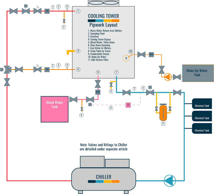
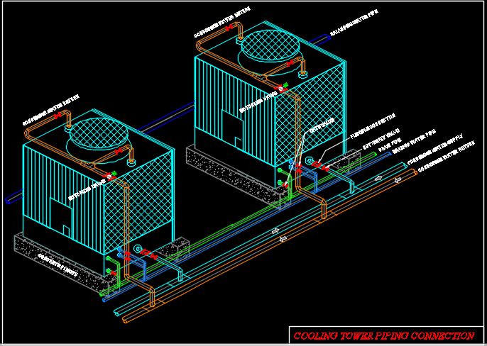
Cooling Tower Piping Layout And Diagrams Constructandcommission Learn how to connect various systems to cooling towers for efficient operation and design. see diagrams and explanations of condenser water return, supply, bypass, equalization, make up, and other pipework configurations. In the design and operation of cooling towers, a piping schematic plays a crucial role in ensuring the efficient and effective cooling of water. this schematic provides a detailed representation of the piping system within a cooling tower, including the flow paths, pipe sizes, valves, and other components. it serves as a roadmap for engineers.

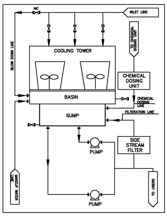
Cooling Tower Piping Schematic Diagram Understanding the basics of piping and controls is step number one in the cooling tower industry. but how effectively a cooling tower piping system is designed and installed can have a critical impact on system efficiency, functionality and even safety. properly engineered condenser, chiller and cooling tower piping and controls will improve heat transfer and avoid problems such as air. Learn about the design and operation of cooling towers and condenser water systems, including performance factors, chiller selection, pump selection, and energy use. see examples, diagrams, and analysis tools for optimal system performance. In a short summary, a cooling tower cools down water that gets over heated by industrial equipment and processes. the hot water is usually caused by air conditioning condensers or other industrial processes. that water is pumped through pipes directly into the cooling tower. A cooling tower flow diagram helps visualise the complex system of the tower and its components. the diagram illustrates the flow of water and air through the tower, as well as the different stages of the cooling process. the cooling tower flow diagram typically begins with the entry of hot water from the industrial process into the tower.

Cooling Tower Piping Schematic Diagram In a short summary, a cooling tower cools down water that gets over heated by industrial equipment and processes. the hot water is usually caused by air conditioning condensers or other industrial processes. that water is pumped through pipes directly into the cooling tower. A cooling tower flow diagram helps visualise the complex system of the tower and its components. the diagram illustrates the flow of water and air through the tower, as well as the different stages of the cooling process. the cooling tower flow diagram typically begins with the entry of hot water from the industrial process into the tower. Learn about evaporative cooling towers, their types, sizing, selection and performance issues. see diagrams of cooling tower components and systems. Learn how to design and operate cooling towers for free cooling applications, which use heat exchangers instead of refrigerant compressors. this bulletin covers system design, capacity control, ice management, and maintenance for induced and forced draft units.

Cooling Tower Heat Transfer Equipment In Process Industry Learn about evaporative cooling towers, their types, sizing, selection and performance issues. see diagrams of cooling tower components and systems. Learn how to design and operate cooling towers for free cooling applications, which use heat exchangers instead of refrigerant compressors. this bulletin covers system design, capacity control, ice management, and maintenance for induced and forced draft units.

Comments are closed.