Cooling Tower Piping Schematic

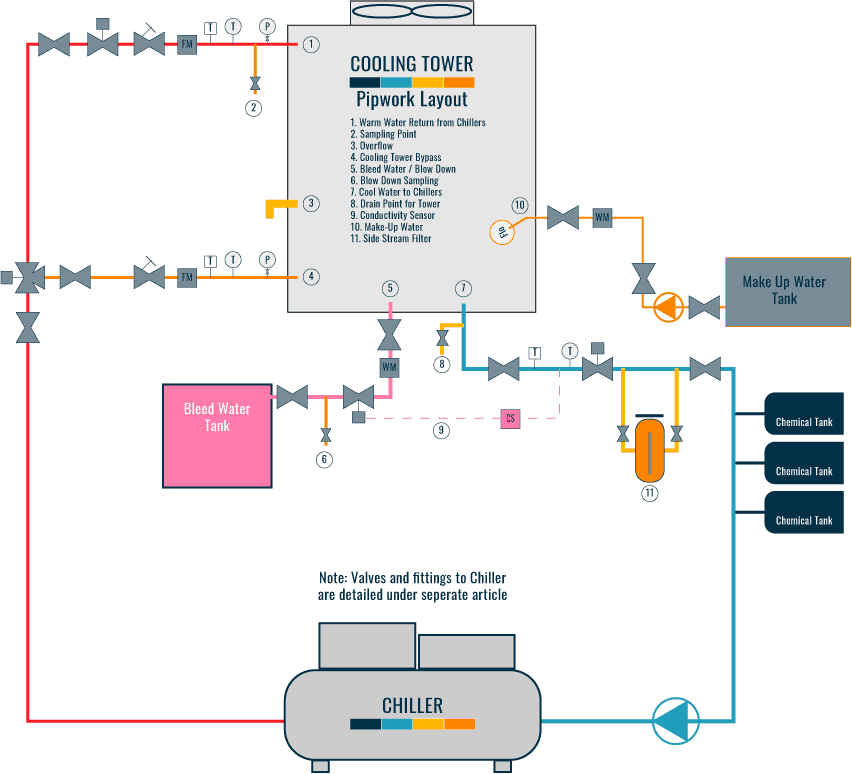
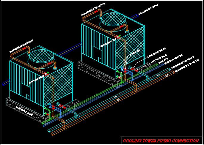
Cooling Tower Piping Layout And Diagrams Constructandcommission Cooling tower typical piping diagram condenser water return pipework [1] the cooling tower return pipework is installed to transport the warm water from the condenser side of the water cooled chiller to the cooling tower, with the flow being provided by the condenser water pumps that are installed on the supply side of the tower [tower to. The cooling tower circuit differs slightly from the basic “open” circuit in that the discharge piping is connected directly to a distribution basin. some towers are furnished with a distribution manifold with nozzles which require additional pressure. figure 3 typical “open” tower piping.

Cooling Tower Piping Schematic Diagram In the design and operation of cooling towers, a piping schematic plays a crucial role in ensuring the efficient and effective cooling of water. this schematic provides a detailed representation of the piping system within a cooling tower, including the flow paths, pipe sizes, valves, and other components. it serves as a roadmap for engineers. Sequence of operation. when the operating fan(s) are operating at 50 percent speed, an additional fan shall be enabled and controlled at the same speed as the operating fans until all active cooling tower cell fans are enabled. when operating fans are running at minimum speed and the tower supply water temperature is five (5) degrees below the. The cooling tower piping schematic diagram breaks the cooling tower system into several distinct pieces. first, the piping associated parts are identified. this includes pipes, fittings, valves, pumps, and other instruments which all play an important role in cooling tower operations. the second portion of the diagram identifies the central. Understanding the basics of piping and controls is step number one in the cooling tower industry. but how effectively a cooling tower piping system is designed and installed can have a critical impact on system efficiency, functionality and even safety. properly engineered condenser, chiller and cooling tower piping and controls will improve heat transfer and avoid problems such as air.

Cooling Tower Piping Schematic Diagram The cooling tower piping schematic diagram breaks the cooling tower system into several distinct pieces. first, the piping associated parts are identified. this includes pipes, fittings, valves, pumps, and other instruments which all play an important role in cooling tower operations. the second portion of the diagram identifies the central. Understanding the basics of piping and controls is step number one in the cooling tower industry. but how effectively a cooling tower piping system is designed and installed can have a critical impact on system efficiency, functionality and even safety. properly engineered condenser, chiller and cooling tower piping and controls will improve heat transfer and avoid problems such as air. Cooling tower piping: when designing a cooling tower system for free cooling applications, several piping details should be considered to ensure proper winter operation of the unit. a cooling tower bypass needs to be incorporated into the system design to allow water to “bypass” the tower’s water distribution system as a means of capacity. Circulating rate, 18°f cooling range. to maintain 4 concentrations, the required blowdown is 0.458% or. 00458 times 700 gpm, which is 3.2 gpm.if tower is operated at 4 concentrations, circulating water will contain four times as much dissolved solid as the makeup water, assuming none of the solids form scale or.

Comments are closed.