Data Flow Diagram Everything You Need To Know About Dfd

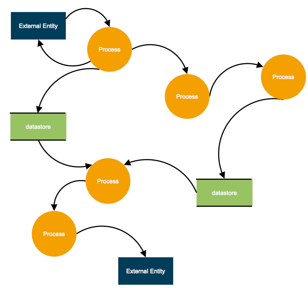
Data Flow Diagram Everything You Need To Know About Dfd Dfd layers. draw data flow diagrams can be made in several nested layers. a single process node on a high level diagram can be expanded to show a more detailed data flow diagram. draw the context diagram first, followed by various layers of data flow diagrams. dfd levels. the first level dfd shows the main processes within the system. Introduction. data flow diagrams (dfds) serve as a time tested and traditional visual representation, offering a comprehensive insight into the intricate web of information flows within a system. this graphical tool is instrumental in illustrating how data navigates through the various facets of an information system, encompassing processes.

Understanding Dfd Data Flow Diagrams With Dfd Functions And Symbols Im A data flow diagram (dfd) maps out the flow of information for any process or system. it uses defined symbols like rectangles, circles and arrows, plus short text labels, to show data inputs, outputs, storage points and the routes between each destination. data flowcharts can range from simple, even hand drawn process overviews, to in depth. A physical data flow diagram visualizes how business systems are implemented in real world terms. it explains how data moves through the system and details the software, hardware, and files involved in the process. physical data flow diagrams provide a deeper insight into system architecture and operational details. Dfd examples: context data flow diagram (level 0): this high level overview uses a single process to represent the entire system’s functions. an example for a clothes ordering system is illustrated below: steps for creating context dfd: define the process. create a list of external entities. list data flows. draw the diagram. level 1 data. To create new dfd, select diagram > new from the toolbar. in the new diagram window, select data flow diagram and click next. enter context as diagram name and click ok to confirm. we'll now draw the first process. from the diagram toolbar, drag process onto the diagram. name the new process system.

Comments are closed.