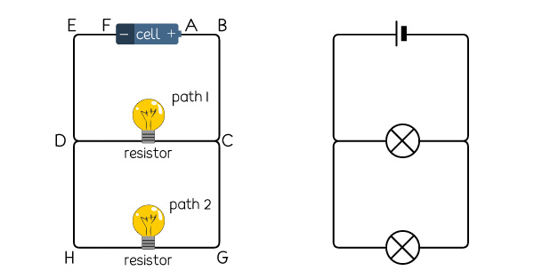
Drawing A Parallel Circuit

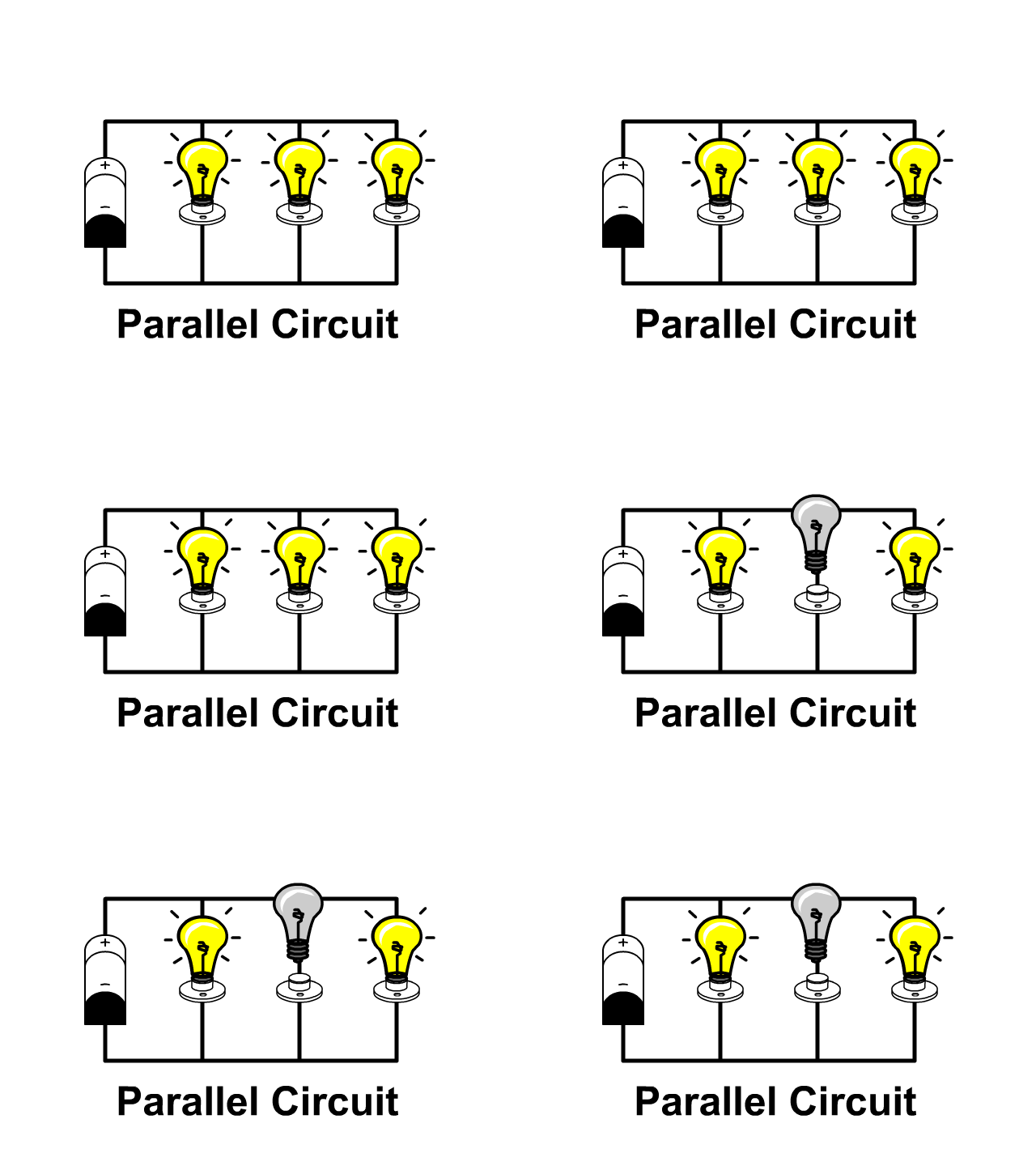
Schematic Diagram Of A Parallel Circuit This is the second principle of parallel circuits: the total parallel circuit current equals the sum of the individual branch currents. how to calculate total resistance in a parallel circuit. by applying ohm’s law to the total circuit with voltage (9 v) and current (14.4 ma), we can calculate the total effective resistance of the parallel. One of the most common examples of parallel circuits is the electrical wiring in your home, particularly the lighting system. each light has its own path to the power source. this setup ensures that if one light burns out or a switch is turned off, the current can still flow to the other lights, keeping them on.

How To Draw A Parallel Circuit Diagram In a parallel circuit, each device is connected in a manner such that a single charge passing through the circuit will only pass through one of the resistors. this lesson focuses on how this type of connection affects the relationship between resistance, current, and voltage drop values for individual resistors and the overall resistance, current, and voltage drop values for the entire circuit. Strategy. the three resistors are connected in parallel and the voltage drop across them is vbattery. thus, we can apply the equation for the equivalent resistance of resistors in parallel, which takes the form. r equiv = 1 1 r 1 1 r 2 1 r 3 . 19.29. the circuit with the equivalent resistance is shown below. In this tutorial, we’ll first discuss the difference between series circuits and parallel circuits, using circuits containing the most basic of components resistors and batteries to show the difference between the two configurations. we’ll then explore what happens in series and parallel circuits when you combine different types of. Introduction to parallel circuits—a parallel circuit example. let’s look at an example of a parallel circuit as shown in figure 4. figure 4. example of a parallel circuit. again, we have three resistors, but this time there are three loops for the current to flow from the positive battery terminal back to the negative terminal: 1–2–7.

Parallel Circuit Definition Parallel Circuit Examples Electrical In this tutorial, we’ll first discuss the difference between series circuits and parallel circuits, using circuits containing the most basic of components resistors and batteries to show the difference between the two configurations. we’ll then explore what happens in series and parallel circuits when you combine different types of. Introduction to parallel circuits—a parallel circuit example. let’s look at an example of a parallel circuit as shown in figure 4. figure 4. example of a parallel circuit. again, we have three resistors, but this time there are three loops for the current to flow from the positive battery terminal back to the negative terminal: 1–2–7. Then, draw a circuit with several components on the board (see figure 3 for an example sketch). ask the class to identify which components of the circuit are connected in series and which are connected in parallel. figure 3. a circuit diagram composed of a battery and three resistors demonstrating series and parallel circuit components. Where series components all have equal currents running through them, parallel components all have the same voltage drop across them series:current::parallel:voltage. series and parallel circuits working together. from there we can mix and match. in the next picture, we again see three resistors and a battery.

Series Parallel Circuit Series Parallel Circuit Examples Electrical Then, draw a circuit with several components on the board (see figure 3 for an example sketch). ask the class to identify which components of the circuit are connected in series and which are connected in parallel. figure 3. a circuit diagram composed of a battery and three resistors demonstrating series and parallel circuit components. Where series components all have equal currents running through them, parallel components all have the same voltage drop across them series:current::parallel:voltage. series and parallel circuits working together. from there we can mix and match. in the next picture, we again see three resistors and a battery.

Diagram Of Electrical Circuit In Parallel

Comments are closed.