Example Of Erd Diagram For Database Ermodelexample
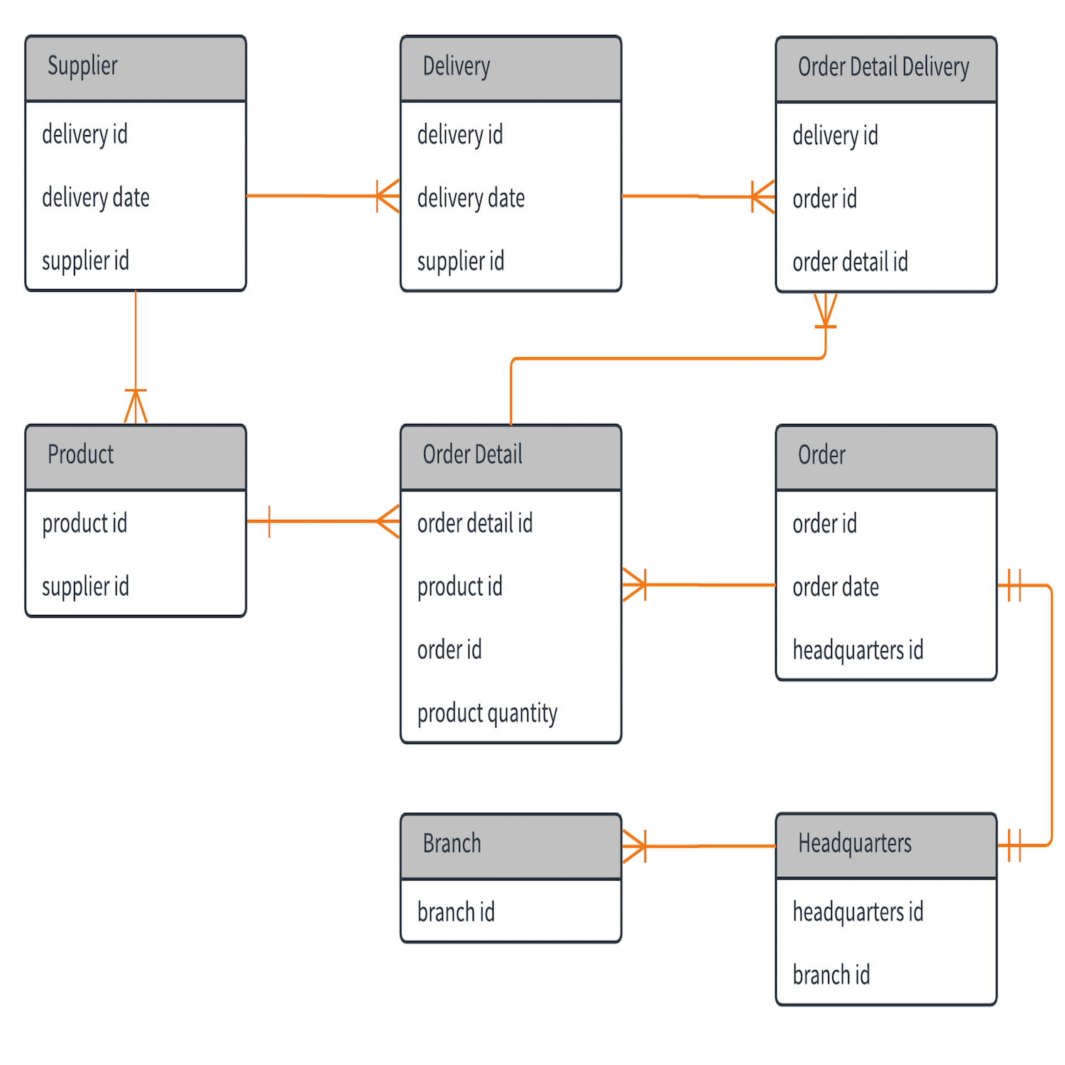
Example Of Erd Diagram For Database Ermodelexample Er diagram stands for entity relationship diagram, also known as erd is a diagram that displays the relationship of entity sets stored in a database. in other words, er diagrams help to explain the logical structure of databases. er diagrams are created based on three basic concepts: entities, attributes and relationships. It's much easier to use ai for populating content in the er diagram example template. follow these steps to effectively use the template: step 1: enter your database topic: specify your database scenario or industry for ai to generate relevant content. step 2: edit ai generated diagram: refine the er diagram through chat, adjusting entities and.
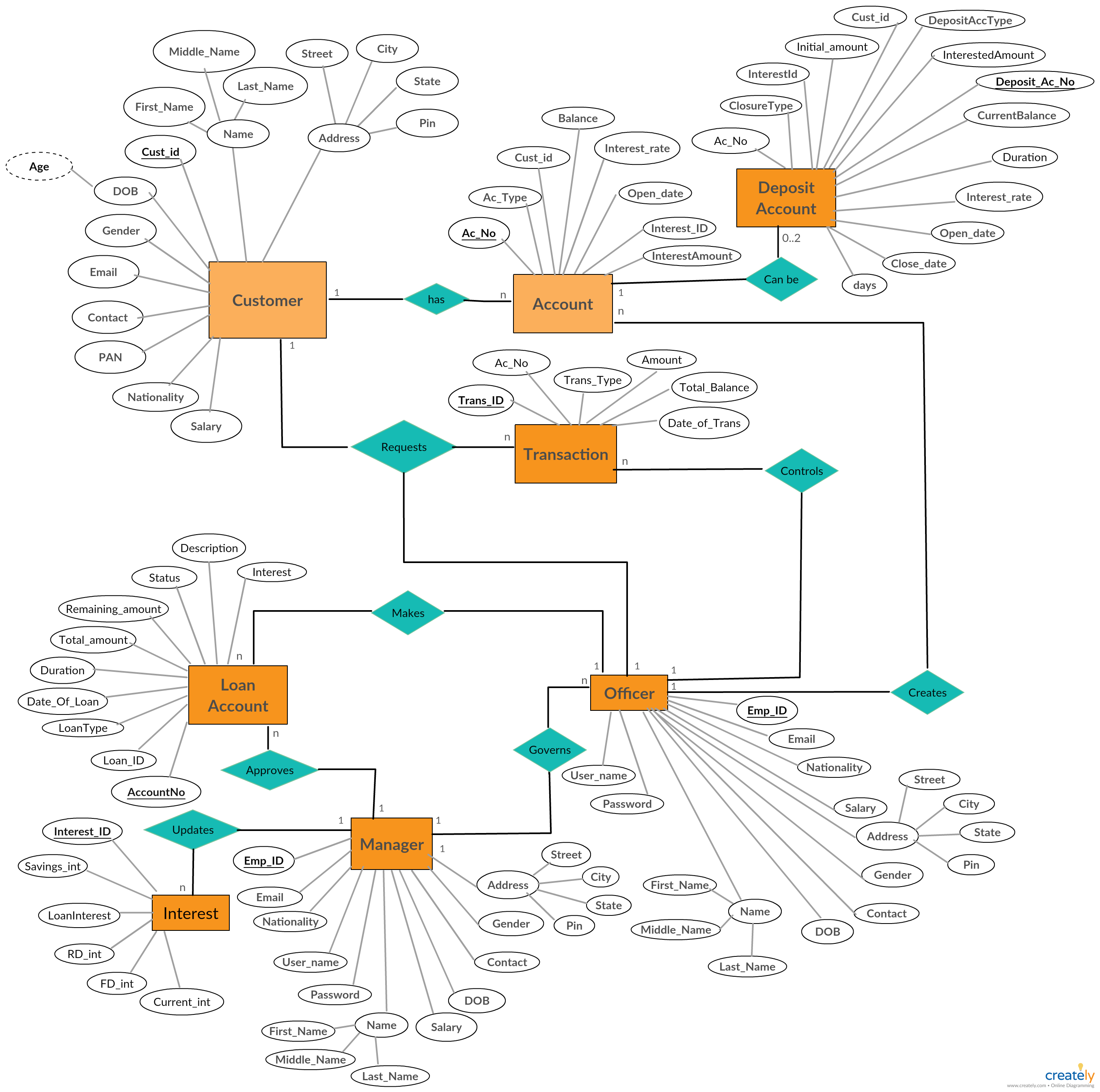
Er Diagram Database Design Ermodelexample These examples will showcase different scenarios and demonstrate how erd diagrams can be used to solve common problems in database design. one example of an erd diagram is a simple customer and order management system. in this scenario, we have two entities: “customer” and “order”. the erd diagram would represent the relationship. Here’s an example erd using idef1x notation: barker. here’s an example of the symbols used with the barker notation style. here’s an example erd using bachman notation: conceptual, logical, physical. an entity relationship diagram can be drawn at three different levels: conceptual, logical, or physical. Introduction. entity relationship (er) modeling is a powerful tool for designing and representing complex data systems. this modeling technique allows developers to visualize the relationships between different entities in a system and the attributes associated with them. er modeling is widely used in software engineering, database design, and. The inter relationships among these present entities. below is an example of the loan system er diagram: entities: i) borrower ii) loan request ii) lender iv) intermediary. relationship: how the borrower loan request is being captured by the lender, and the lending process takes place.
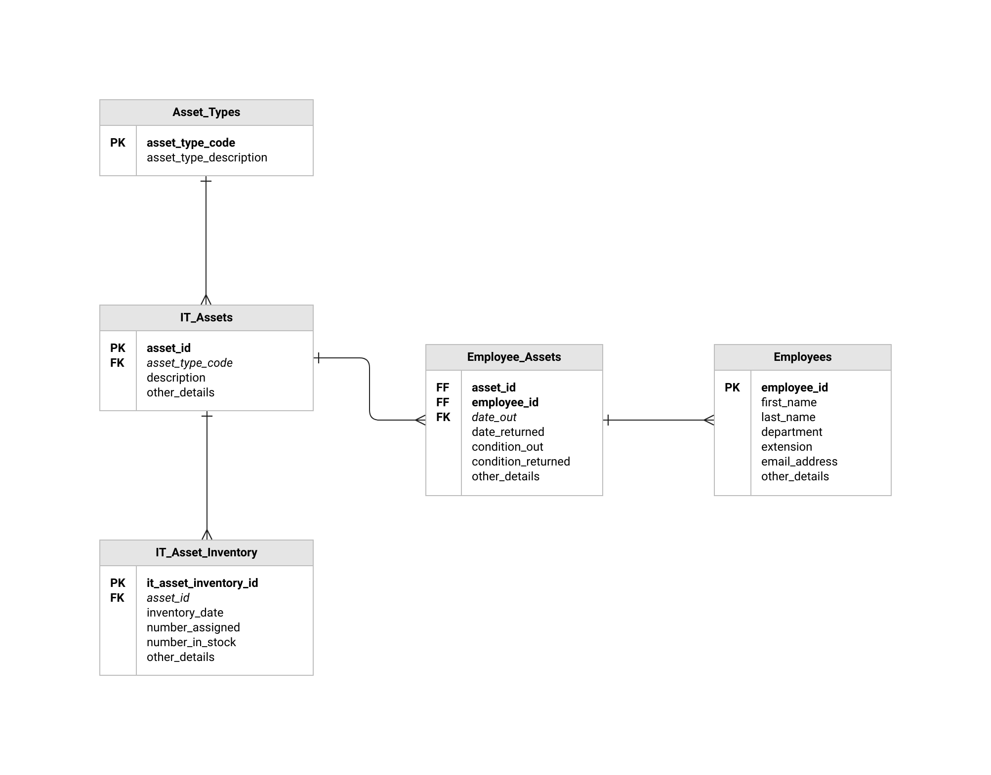
Simple Erd Ermodelexample Introduction. entity relationship (er) modeling is a powerful tool for designing and representing complex data systems. this modeling technique allows developers to visualize the relationships between different entities in a system and the attributes associated with them. er modeling is widely used in software engineering, database design, and. The inter relationships among these present entities. below is an example of the loan system er diagram: entities: i) borrower ii) loan request ii) lender iv) intermediary. relationship: how the borrower loan request is being captured by the lender, and the lending process takes place. Table of contents hide 1 refining entity relationship diagrams (erds) for effective database design 1.1 problem description: er modeling – a car rental company system 2 step by step guide to developing an er diagram for a database 3 understanding the differences between conceptual, logical, and physical data modeling 4 creating the conceptual erd from the problem description […]. Fully customizable. entity relationship diagram, also known as erd, er diagram or er model, is a type of structural diagram for use in database design. an erd contains different symbols and connectors that visualize two important information: the major entities within the system scope, and the inter relationships among these entities.
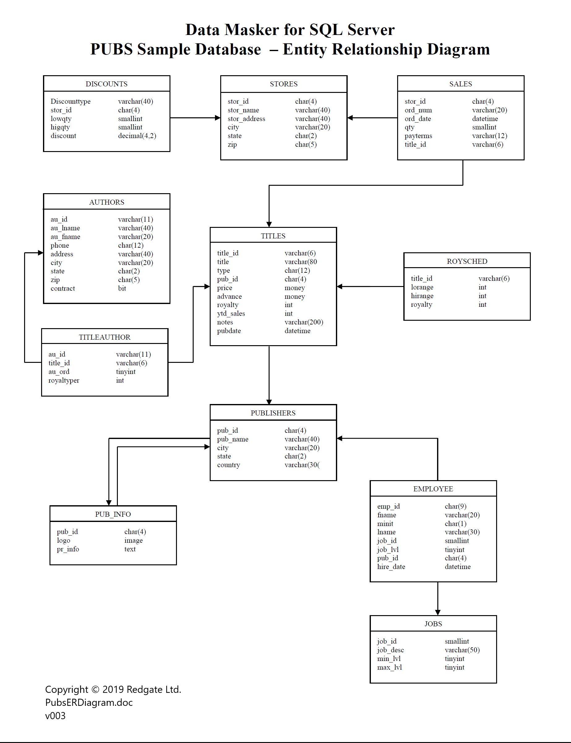
Sample Erd Diagram Database вђ Ermodelexample Table of contents hide 1 refining entity relationship diagrams (erds) for effective database design 1.1 problem description: er modeling – a car rental company system 2 step by step guide to developing an er diagram for a database 3 understanding the differences between conceptual, logical, and physical data modeling 4 creating the conceptual erd from the problem description […]. Fully customizable. entity relationship diagram, also known as erd, er diagram or er model, is a type of structural diagram for use in database design. an erd contains different symbols and connectors that visualize two important information: the major entities within the system scope, and the inter relationships among these entities.
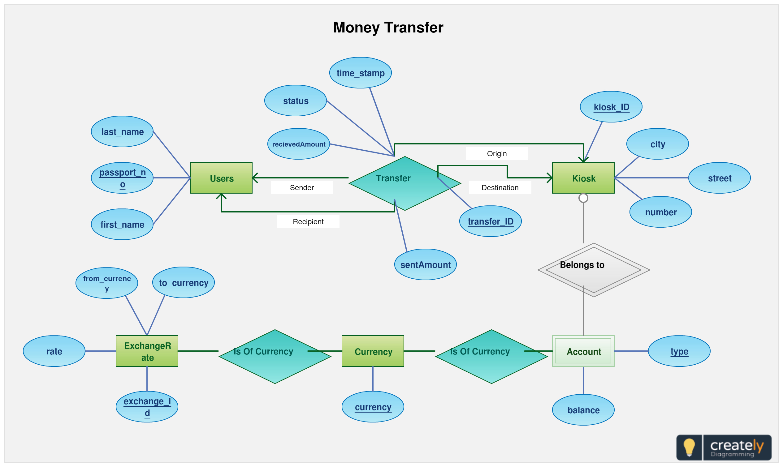
How To Create Erd Diagram Ermodelexample

Comments are closed.