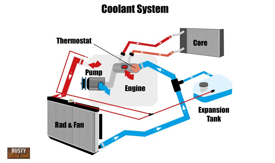
Ford 302 Cooling System Diagram

Understanding The Ford 302 Cooling System A Detailed Diagram The main components of the ford 302 cooling system include the radiator, water pump, thermostat, coolant, hoses, and fan. the radiator is responsible for cooling the hot coolant that flows from the engine. it has a network of tubes and fins that help dissipate heat. the water pump circulates the coolant through the engine and radiator, ensuring. Ford 302 coolant flow diagram. robert. november 2, 2022. the ford 302 engine features a pressurized cooling system to prevent the engine from overheating. the coolant flows through different passages in the engine block and cylinder heads before being pumped back into the radiator. there are two thermostats in the system, one for the engine and.

Understanding The Ford 302 Cooling System A Detailed Diagram 557 posts · joined 2006. #1 · feb 9, 2020. tempered with the old adage that ford never spent a dime he (they) didn’t have to, isn’t the thermostat bypass on the small block ford cooling system (the little 90° hose that runs from the thermostat housing to the water pump) a bit of a redundancy, given that the heater also allows the same. Here's the description from the 1995 service cd. the cooling system operates as follows: l coolant flows through the radiator tubes and is cooled by air passing over the cooling fins assisted by the cooling fan motor and fan blades. l coolant is then circulated from the radiator outlet tank (8054) through the water pump (8501) and into the. Factory ford shop manuals are available from helm publications, 1 800 782 4356 5) coolant flow diagram: if a heater circuit is not used then the heater supply must be connected to the heater return to allow air to be purged from the right hand cylinder head and provide sufficient coolant flow through the right hand cylinder head. Hi, does anyone have a diagram showing the flow of coolant around the engine radiator etc. i have a 302 engine and the two small outlets on the water pump have been bridged i assume these were for the heater matrix, and at the back of the heads there seems to be coolant ways which have been blocked off, i'm worried that this will over heat.

Ford 302 Coolant Flow Diagram Diagraminfo Factory ford shop manuals are available from helm publications, 1 800 782 4356 5) coolant flow diagram: if a heater circuit is not used then the heater supply must be connected to the heater return to allow air to be purged from the right hand cylinder head and provide sufficient coolant flow through the right hand cylinder head. Hi, does anyone have a diagram showing the flow of coolant around the engine radiator etc. i have a 302 engine and the two small outlets on the water pump have been bridged i assume these were for the heater matrix, and at the back of the heads there seems to be coolant ways which have been blocked off, i'm worried that this will over heat. Fuel system and related parts (evaporative emission system (with in cab fuel tank) 1970 f100 6 cyl. 240, 300 and 8 cyl. 302, 360, 390 engines. 1200 x 1498, 301k: fuel system and related parts (evaporative emission system (with in cab fuel tank) 1971 1972 f100 6 cyl. 240, 300 and 8 cyl. 302, 360, 390 engines. 1172 x 1605, 325k. 303 03a 2 303 03a 3. erationengine coolingnotice:the engine cooling system is filled with motorcra. t premium gold engine coolant. mixing coolant types degrades the corrosion protection of motorcra. system components include t. :block heater (if equipped).engine co. ant temperature (ect) sensor.cooling. an motor.

Understanding The Ford 302 Cooling System A Detailed Diagram Fuel system and related parts (evaporative emission system (with in cab fuel tank) 1970 f100 6 cyl. 240, 300 and 8 cyl. 302, 360, 390 engines. 1200 x 1498, 301k: fuel system and related parts (evaporative emission system (with in cab fuel tank) 1971 1972 f100 6 cyl. 240, 300 and 8 cyl. 302, 360, 390 engines. 1172 x 1605, 325k. 303 03a 2 303 03a 3. erationengine coolingnotice:the engine cooling system is filled with motorcra. t premium gold engine coolant. mixing coolant types degrades the corrosion protection of motorcra. system components include t. :block heater (if equipped).engine co. ant temperature (ect) sensor.cooling. an motor.

Understanding The Ford 302 Cooling System A Detailed Diagram

Comments are closed.