Gy6 Wiring Schematic Cdi

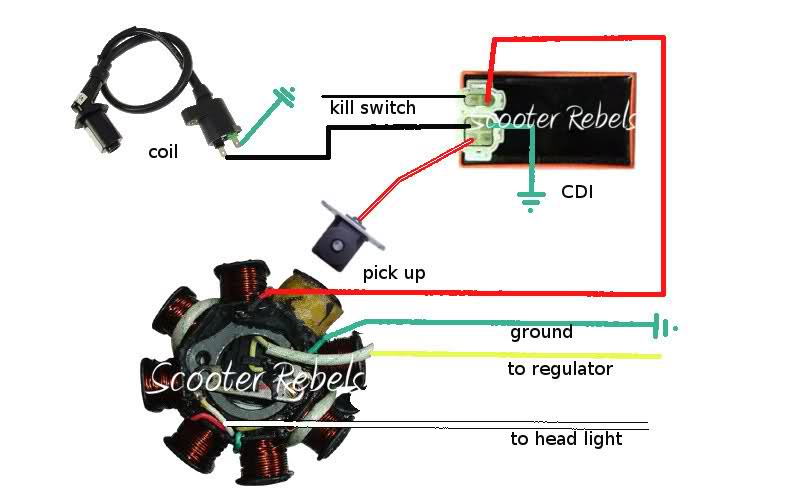
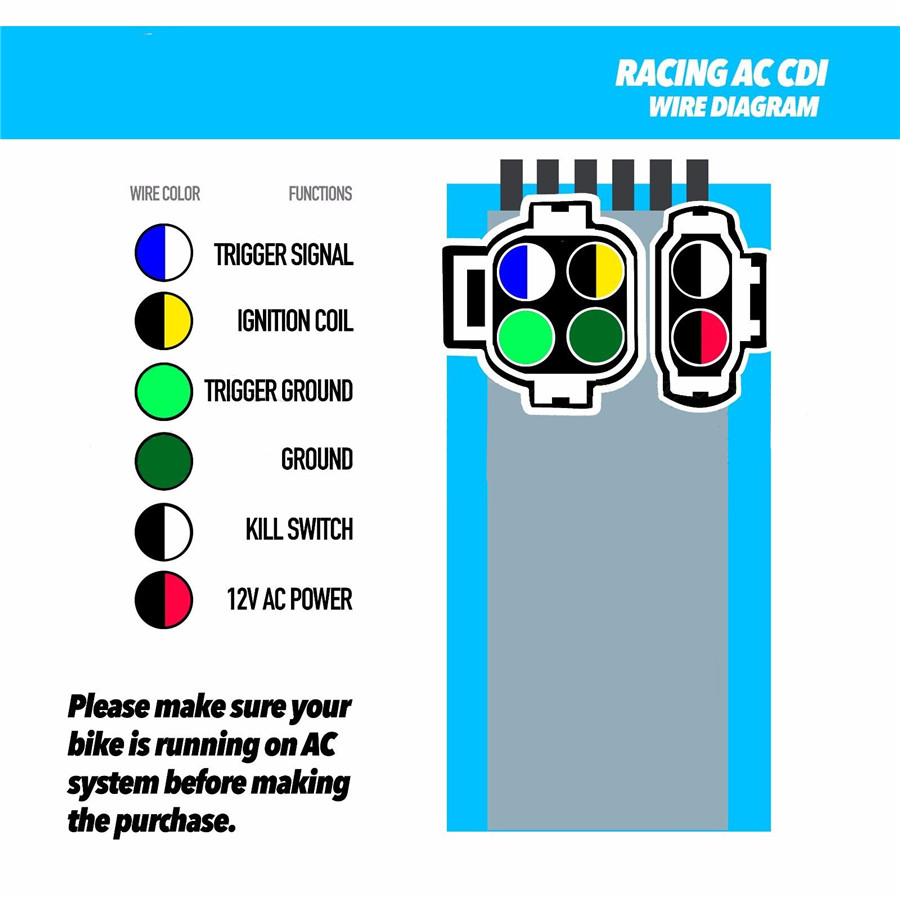
Gy6 Wiring Schematic Cdi One common variation in gy6 cdi wiring diagrams is the number of pins on the cdi connector. some cdi systems may have a 4 pin connector, while others may have a 5 pin or 6 pin connector. these pins correspond to different wires and connections, such as the ignition coil, kill switch, magneto, and other components. The gy6 engine wiring diagram is a visual representation of the electrical system of a gy6 engine, which is commonly found in scooters and atvs. it is a detailed diagram that shows the various components of the electrical system and how they are connected and interact with each other. the diagram includes information about the ignition system.

Gy6 Wiring Schematic 150cc The gy6 wiring diagram is a visual representation of the electrical connections and components within a gy6 engine. it provides a clear and organized layout of the wiring harness, ignition system, charging system, and other essential electrical components. by referring to the wiring diagram, you can easily understand the wiring connections and. Step 4: connect the wires. use wire strippers and crimpers to strip the ends of the wires and attach wire connectors. match the wire colors from the gy6 wiring harness to the corresponding wires on your vehicle, making sure to connect them securely. step 5: solder and insulate. The schematic uses symbols and color codes to represent different electrical components and connections. by referring to the schematic, you can easily identify the components and troubleshoot any problems. one of the key components of the gy6 wiring schematic is the cdi (capacitor discharge ignition) unit. So, i was having a hard time finding good, overall knowledge on stators, magnetos, and general wiring of a cdi unit to a magneto. so, i figured it out, and a.

Gy6 Wiring Schematic Cdi The schematic uses symbols and color codes to represent different electrical components and connections. by referring to the schematic, you can easily identify the components and troubleshoot any problems. one of the key components of the gy6 wiring schematic is the cdi (capacitor discharge ignition) unit. So, i was having a hard time finding good, overall knowledge on stators, magnetos, and general wiring of a cdi unit to a magneto. so, i figured it out, and a. This video is a breakdown of what a cdi box is for the gy6 and other small engines. i go through what the cdi box does, how to tell if you have an ac or dc v. The common wiring diagram for a dc cdi includes four wires two for the stator coil, one for the pick up coil, and one for the trigger wire. the stator coil provides power to the cdi, while the pick up coil senses the engine's rpm and sends a signal to the cdi to fire the spark plug at the right time. the trigger wire, usually green, is.

Comments are closed.