How To Make 8 Pin Relay In Light Wiring Diagram Wiring A 8 Pi

How To Make 8 Pin Relay In Light Wiring Diagram Wiringо Make sure the wires are properly insulated and can handle the electrical load. next, identify the different pins on the relay. typically, an 8 pin relay has two power pins, two coil pins, and four contact pins. the power pins are usually labeled as “ v” and “gnd” or “com” (common). Start by gathering all the necessary components for the wiring, including the 8 pin relay, the relay base, and the wires. locate the pins on the relay base and identify their functions. typically, an 8 pin relay base consists of eight pins with labels such as a1, a2, b1, b2, c1, c2, etc. connect the wires to the corresponding pins on the relay.

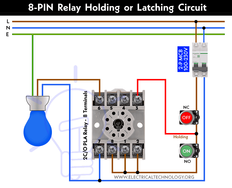
Wiring A Relay With 8 Pins Simplified Guide This diagram provides a full view of the process of connecting a relay to other components, as well as a detailed look at the individual pins involved. with this information, you can make sure your system is up and running safely and efficiently. the 8 pin relay wiring diagram is composed of two parts – the schematic and the wiring diagram. Circuit diagram. below is the step by step guide to wire a latching or holding circuit using 8 pin relay according to the given circuit diagram. connect the phase wire from the two poles mcb (100 230v ac breaker) to the 2, 1 & 8 terminals of the relay. similarly, wire the neutral wire from the mcb to the 7 terminal of the relay. The relay consists of eight pins that are used for different purposes. these pins are typically labeled with numbers or letters to indicate their function. pin numbers 1, 2, and 3 are used for the control circuit, while pins 4 and 5 are used for the coil circuit. pins 6, 7, and 8 are used for the switching circuit. A light relay wiring diagram provides a visual representation of how the various parts of a relay system are connected. this diagram helps electricians and technicians understand the wiring configuration and troubleshoot any potential issues. a light relay is an electromechanical switch that controls the flow of electricity to the lights.

8 Pin Relay Wiring Diagram 8 Pin Relay Connection ођ The relay consists of eight pins that are used for different purposes. these pins are typically labeled with numbers or letters to indicate their function. pin numbers 1, 2, and 3 are used for the control circuit, while pins 4 and 5 are used for the coil circuit. pins 6, 7, and 8 are used for the switching circuit. A light relay wiring diagram provides a visual representation of how the various parts of a relay system are connected. this diagram helps electricians and technicians understand the wiring configuration and troubleshoot any potential issues. a light relay is an electromechanical switch that controls the flow of electricity to the lights. The 8 pin relay circuit diagram below shows how an 8 pin relay is wired to a circuit. the coil of the relay is connected to the positive terminal of the battery, and the contacts are connected to the load (in this case, a light bulb). when the switch is closed, electricity flows through the coil of the relay, creating a magnetic field that. Step 1: power connection. the first step is to connect the power supply to the relay module. check the diagram to identify the power input terminals, usually labeled as vcc and gnd. connect the positive terminal of the power supply to the vcc pin and the negative terminal to the gnd pin.

How To Wire 8 Pin Relay For Holding Or Latching Circuit The 8 pin relay circuit diagram below shows how an 8 pin relay is wired to a circuit. the coil of the relay is connected to the positive terminal of the battery, and the contacts are connected to the load (in this case, a light bulb). when the switch is closed, electricity flows through the coil of the relay, creating a magnetic field that. Step 1: power connection. the first step is to connect the power supply to the relay module. check the diagram to identify the power input terminals, usually labeled as vcc and gnd. connect the positive terminal of the power supply to the vcc pin and the negative terminal to the gnd pin.

24v 8 Pin Relay Wiring Diagram Wiring Diagram

Comments are closed.