Hvac Electrical Schematic Symbols
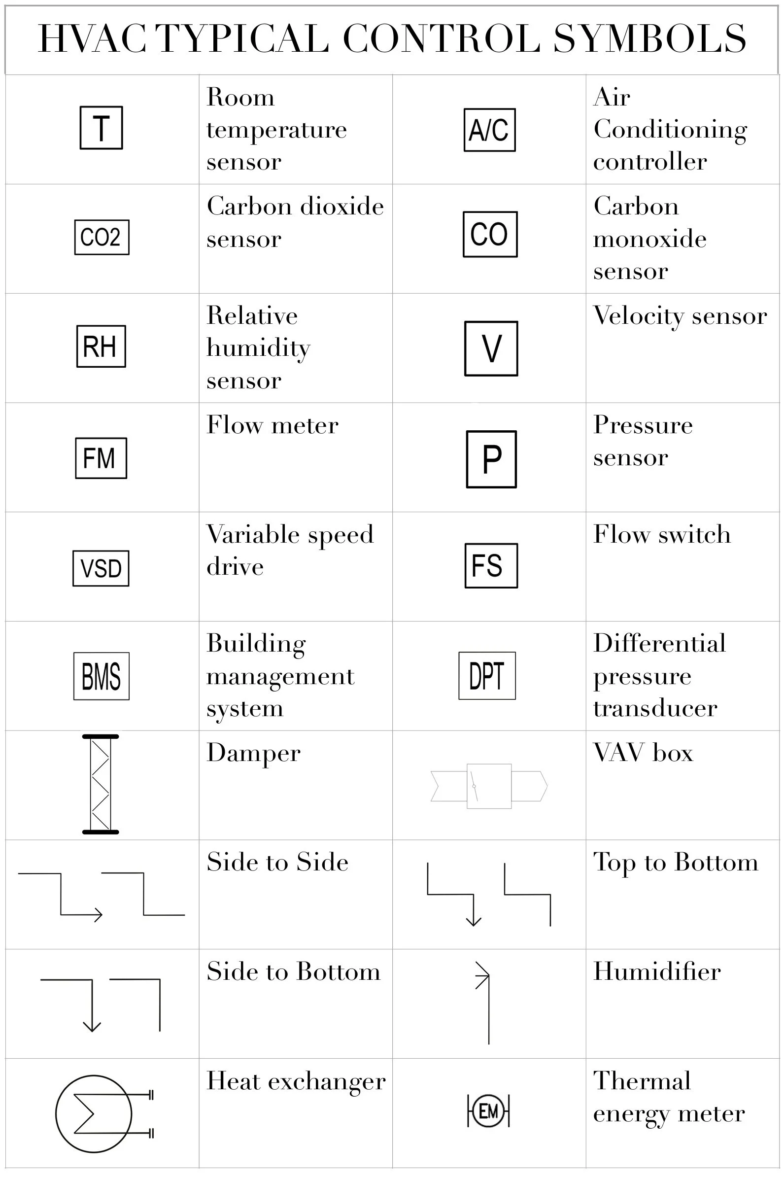
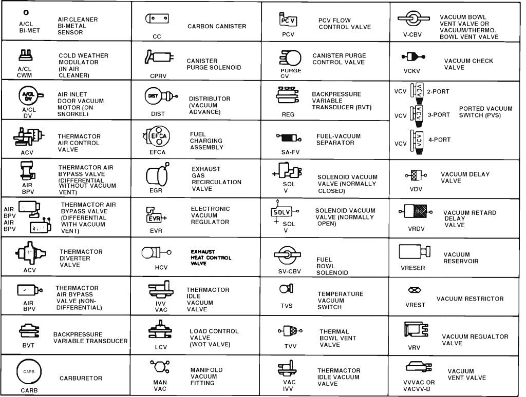
Hvac Schematic Symbols Chart One of the key aspects of hvac electrical diagrams is the use of symbols to represent various components. these symbols, also known as electrical schematic symbols, are standardized and serve as a universal language for technicians. for example, a resistor is represented by a zigzag line, while a capacitor is denoted by two parallel lines. The hvac schematic symbols chart includes a wide range of symbols that represent different types of equipment, such as motors, valves, dampers, pumps, and sensors. each symbol has a specific meaning, allowing professionals to quickly identify and troubleshoot issues within a system. for example, a motor symbol represents a motor used in an hvac.

Hvac Electrical Symbols Chart Pdf Hvac wiring diagram and legend. we’ll jump right into showing you a schematic diagram for a simple air conditioning unit. we’ll make a ladder diagram using a simple air conditioner as our example. first we have the main electrical supply lines l1 and l2 providing 208 230 volt, single phase power. then we’ll need a transformer to provide. The symbol for 4 way ceiling diffuser is a square box with 4 arrows pointing at north, south, east and west directions. the 4 way ceiling diffuser symbol can be found in the layout drawings. the arrows indicate the supply air direction. if there are only 2 arrows, it means the supply air blows on two sides only. In hvac wiring diagrams, the symbol for the power supply represents the electrical source that provides the necessary energy to operate the heating, ventilation, and air conditioning system. this symbol typically consists of a straight line with a small circle at the end, indicating the connection point to the power source. May 22, 2024. when troubleshooting a malfunctioning hvac system, it’s important to understand hvac symbols. these symbols, found in electrical and electronic schematics, guide the design and repair of the system’s circuit boards and wiring. you can become familiar with these symbols by reading your hvac system manual.

A Comprehensive Guide To Hvac Schematic Symbols Decoding The Chart For In hvac wiring diagrams, the symbol for the power supply represents the electrical source that provides the necessary energy to operate the heating, ventilation, and air conditioning system. this symbol typically consists of a straight line with a small circle at the end, indicating the connection point to the power source. May 22, 2024. when troubleshooting a malfunctioning hvac system, it’s important to understand hvac symbols. these symbols, found in electrical and electronic schematics, guide the design and repair of the system’s circuit boards and wiring. you can become familiar with these symbols by reading your hvac system manual. The hvac schematic symbols chart typically includes symbols for various equipment such as fans, motors, compressors, valves, ductwork, and electrical components. each symbol represents a specific item or function within the hvac system, allowing technicians and engineers to quickly identify the various components and their roles in the system. Reading hvac schematics requires understanding symbols and their connections. start by identifying key components like compressors, heat exchangers, and fans. next, analyze how these parts connect through ducts and wiring. this helps in visualizing the system’s operation.

Hvac Electrical Schematic Symbols The hvac schematic symbols chart typically includes symbols for various equipment such as fans, motors, compressors, valves, ductwork, and electrical components. each symbol represents a specific item or function within the hvac system, allowing technicians and engineers to quickly identify the various components and their roles in the system. Reading hvac schematics requires understanding symbols and their connections. start by identifying key components like compressors, heat exchangers, and fans. next, analyze how these parts connect through ducts and wiring. this helps in visualizing the system’s operation.

Comments are closed.