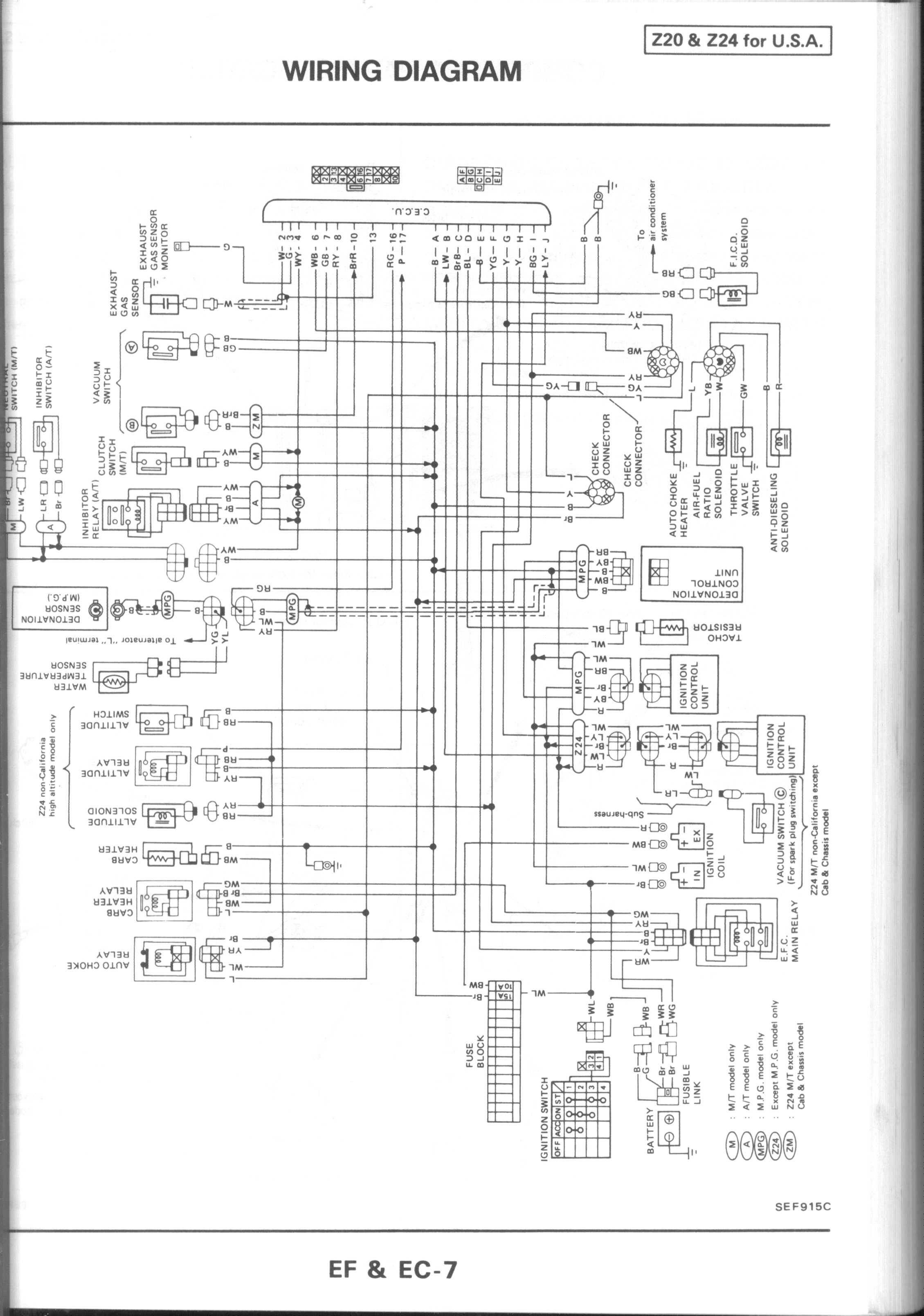
Ka24e Coolant Hose Diagram

Ka24e Coolant Hose Diagram Remove both the upper and lower radiator hoses from the car. disconnect any other coolant hoses that you can currently reach. 13. remove the 3 12mm bolts and 2 12mm nuts from where the runners and the collector meet. remove the 8 12mm bolts and 2 12mm nuts from where the mani goes into the head. 14. Re: ka24de intake manifold vacuum coolant hose location diagram (jt15833) post by supra33202 » thu jul 30, 2009 2:22 pm. i would like to know too. car: 1990 240sx ka24de t swap 8.6:1cr ,duelsprings ,ti retainers,supertech pistons,k1 h beems balanced internals ect ect.

Ka24e Coolant Hose Diagram If you get the hoses from frsport (3 hoses blue tips) get a hose fitting with a nipple on the other. next get about 4 feet of heater hose because its cheap and works well. cut the lines in the center that is just below the butterfly portion of the intake. insert a double nipple 3 8ths hose connector with hose clamps connecting it all pictures. By ispypsi » tue mar 27, 2007 2:57 am. large upper one pointing back uses a "c" loop to connect to large opening behind t stat. this is to help loop coolant when t stat is closed and heater is closed. small port on upper pointing to side runs to throttle body, once it comes out the other side, it branches into a hardline under the plenum, near. I believe 4 and 5 is a straight pass through for throttle body coolant and i will leave these alone (possibly block to keep debris out). 6 will stay for coolant, 7 is throttle body and will be covered, and 8 will stay as well. 9 will have a sensor put in place. block connections 1 coolant connects to heater core outlet 2 coolant to. Article. disconnect negative battery cable. drain oil and coolant. disconnect all related pipes, electrical harnesses, vacuum lines and fuel lines. remove a c compressor and power steering pump without disconnecting hoses and set aside. 2) remove alternator and adjusting bracket. raise and support vehicle. remove drive shaft on 4wd models.

Ka24e Coolant Hose Diagram Wiring Diagram Pictures I believe 4 and 5 is a straight pass through for throttle body coolant and i will leave these alone (possibly block to keep debris out). 6 will stay for coolant, 7 is throttle body and will be covered, and 8 will stay as well. 9 will have a sensor put in place. block connections 1 coolant connects to heater core outlet 2 coolant to. Article. disconnect negative battery cable. drain oil and coolant. disconnect all related pipes, electrical harnesses, vacuum lines and fuel lines. remove a c compressor and power steering pump without disconnecting hoses and set aside. 2) remove alternator and adjusting bracket. raise and support vehicle. remove drive shaft on 4wd models. Re: ka24e vacuum diagram (jp240sx) post by neverlift » fri may 25, 2007 2:34 pm. come on guys. you rfuel pressure regulator and brake booster lines are the only ones you need for s13's. just cap em all off disconnect whatever. top. Msrp: $1.90. $1.43. add to cart. 08126 8161e. bolt hex. genuine nissan parts, the right choice. nissanpartsdeal offers the wholesale prices for genuine 1995 nissan hardbody pickup (d21u) parts. parts like water hose & piping are shipped directly from authorized nissan dealers and backed by the manufacturer's warranty.

Comments are closed.