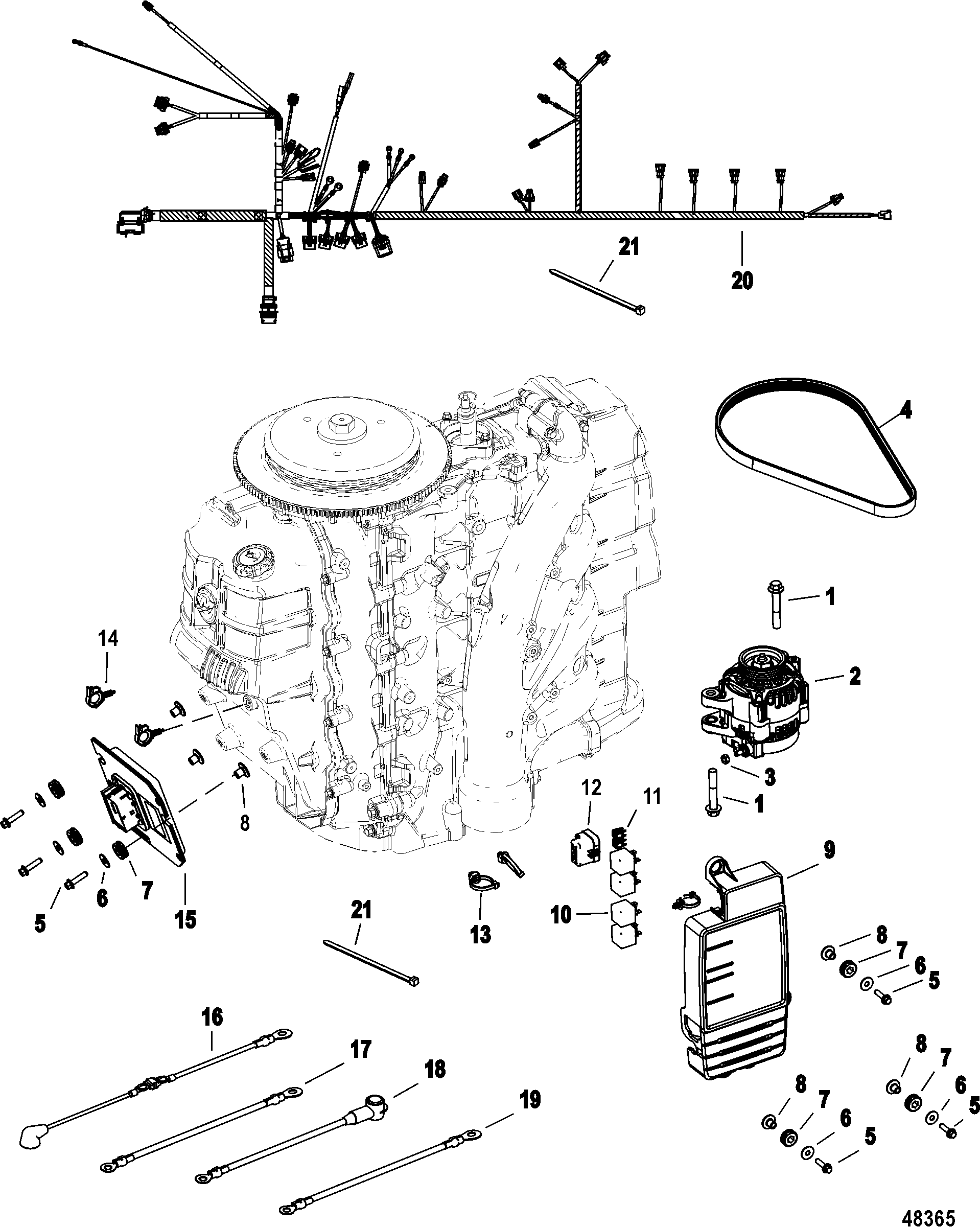
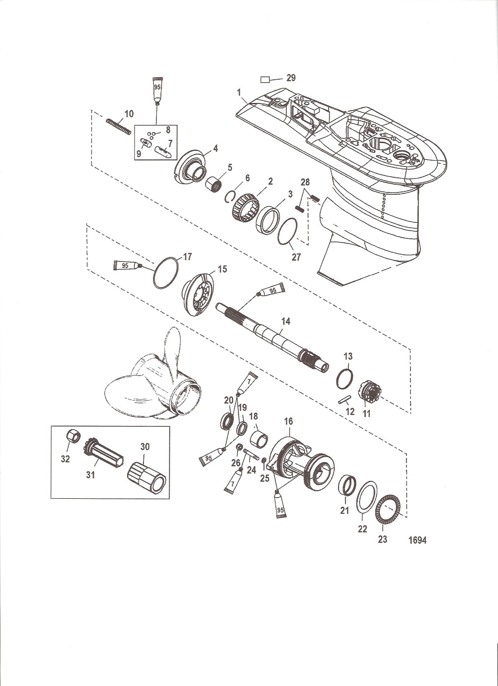
Mercury Optimax Wiring Diagram

Wiring Diagram For Mercury Optimax 2. attach throttle cable to the throttle lever. secure with washer and locknut. 57837 washer and locknut – tighten locknut and back off 1 4 turn 3. adjust the cable barrel so that the installed throttle cable will hold the idle stop screw against the stop. View and download mercury optimax 115 service manual online. direct fuel injection. optimax 115 outboard motor pdf manual download. also for: optimax 135, optimax 150, optimax 175.

Mercury 150 Optimax Wiring Diagram Mercury 200 optimax jet drive service manual (since 2001) [pdf, eng, 16.3 mb].pdf looking for a repair manual with wiring diagram for a 2015 mercury 150 hp, efi. 2.5 litre optimax 2000 & 2001 model year fuel & air flow diagram. fuel inlet to high pressure electric fuel pump. fuel injector is opened by the ecm, 90 psi (620 kpa) fuel is discharged into a machined cavity inside the air chamber of the air fuel rail. this mixes the fuel with the air charge. 200 225 optimax dts 3. connect a hoist to the lifting eye. 4. lift the outboard and place it on the boat transom. applying counter rotation decals important: for dual outboard counter rotation installation, the left hand rotation outboard is generally placed on the port sided of the transom. 250 optimax jet drive engine wiring 1. ecm 2. ignition coils 3. coil drivers 4. fuel injectors 5. direct injectors 6. oil pump 7. map sensor 8. block pressure sensor.

Mercury 225 Optimax Wiring Diagram 200 225 optimax dts 3. connect a hoist to the lifting eye. 4. lift the outboard and place it on the boat transom. applying counter rotation decals important: for dual outboard counter rotation installation, the left hand rotation outboard is generally placed on the port sided of the transom. 250 optimax jet drive engine wiring 1. ecm 2. ignition coils 3. coil drivers 4. fuel injectors 5. direct injectors 6. oil pump 7. map sensor 8. block pressure sensor. The system is activated when the oil in the engine mounted oil reservoir tank drops below 22 fl. oz. (175 ml) you still have an oil reserve remaining for 30 minutes of full speed opera tion. note: the engine mounted oil reservoir tank (located beneath the top cowl) along with the remote oil tank will have to be refilled. The system is activated when there is an electrical failure of the oil pump or the oil pump circuit. stop the engine as soon as possible. continuing to operate the engine can result in severe engine damage. the oil light (a) and check engine light (b) will come on and the warning horn will be gin sounding.

Comments are closed.