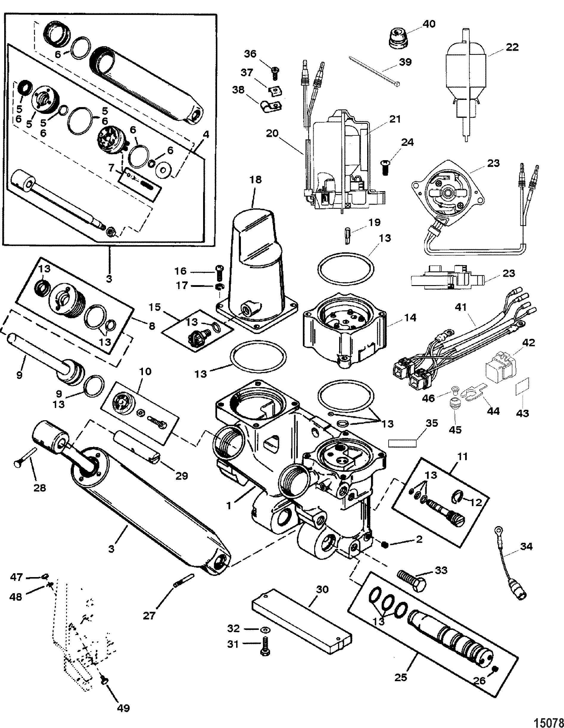
Mercury Tilt Trim Schematic

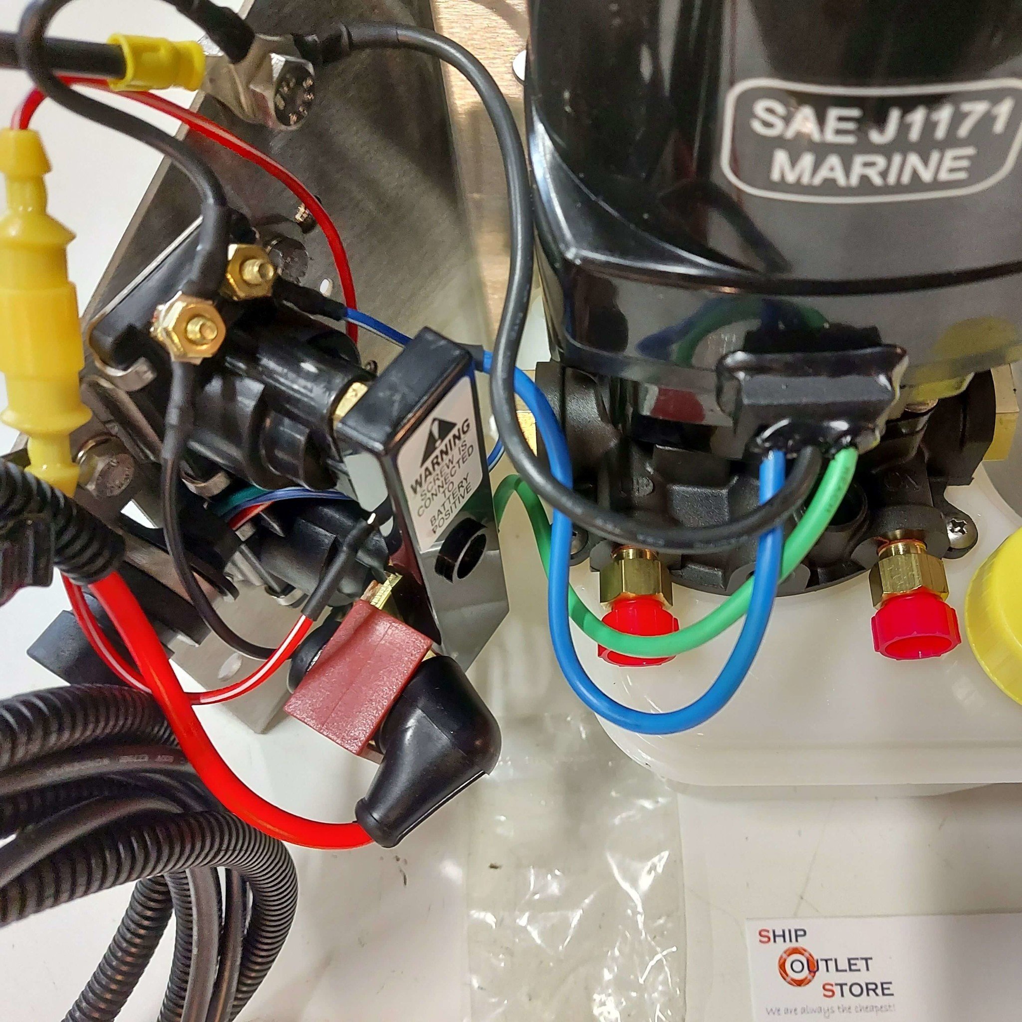
Mercury Tilt Trim Schematic Identify and locate the wires for the tilt trim system on the mercury outboard. these wires are typically color coded and will include power, ground, and control wires. 4. strip the wires. using the wire cutters, carefully strip a small portion of insulation from the ends of the wires to expose the bare metal. The tilt and trim system allows you to adjust the position of your outboard motor, providing you with better control and performance on the water. in this step by step guide, we will walk you through the process of understanding and connecting the wires in the mercury tilt and trim system. before we dive into the wiring diagram, it’s.

Mercury Tilt Trim Schematic A mercury tilt and trim system is a crucial component of a boat’s outboard motor, allowing the operator to adjust the angle of the motor for optimal performance and maneuverability. understanding the various components of the tilt and trim system is essential for troubleshooting and maintenance. 1. tilt and trim switch. Step 4: connect the wires. using crimp connectors, connect the wires according to the trim gauge wiring diagram. ensure a proper connection by using a multimeter to check for continuity between the connected wires. if the multimeter shows no continuity, double check the connections and make any necessary adjustments. When it comes to installing the mercury tilt and trim gauge, wiring diagrams are invaluable. you must begin by studying the diagram carefully, noting each symbol and connecting point. once familiar with the diagrams, identify where each connection must be made and the proper method for doing so. using diagram symbols such as light bulb, relay. Mariner tilt and trim problem. 5. trim motor not working on 2002 40hp 2 stroke. 1. 60h tilt trim unitframe compatible wothers. 16. power tilt and trim probs. 3. 1978 mercury tilt trim problem.

Mercury Outboard Tilt Wiring Diagram When it comes to installing the mercury tilt and trim gauge, wiring diagrams are invaluable. you must begin by studying the diagram carefully, noting each symbol and connecting point. once familiar with the diagrams, identify where each connection must be made and the proper method for doing so. using diagram symbols such as light bulb, relay. Mariner tilt and trim problem. 5. trim motor not working on 2002 40hp 2 stroke. 1. 60h tilt trim unitframe compatible wothers. 16. power tilt and trim probs. 3. 1978 mercury tilt trim problem. Page 35 mercruiser applications prior to beginning the installation. 1. ensure that the keypad assembly and vcm have been installed as previously outlined. 2. connect the active trim harness to the vcm. refer to vcm connection (all models). 3. connect the keypad assembly to the active trim harness. Activate the trim control switch and observe the movement of the outboard or sterndrive. if the trim motor is working correctly, the angle of the boat’s propulsion system should adjust accordingly. in conclusion, wiring the trim motor requires careful attention to detail and following a step by step guide.

Mercury Tilt And Trim Assembly Diagram Page 35 mercruiser applications prior to beginning the installation. 1. ensure that the keypad assembly and vcm have been installed as previously outlined. 2. connect the active trim harness to the vcm. refer to vcm connection (all models). 3. connect the keypad assembly to the active trim harness. Activate the trim control switch and observe the movement of the outboard or sterndrive. if the trim motor is working correctly, the angle of the boat’s propulsion system should adjust accordingly. in conclusion, wiring the trim motor requires careful attention to detail and following a step by step guide.

Comments are closed.