Motor Control Circuit Wiring Instrumentation Tools

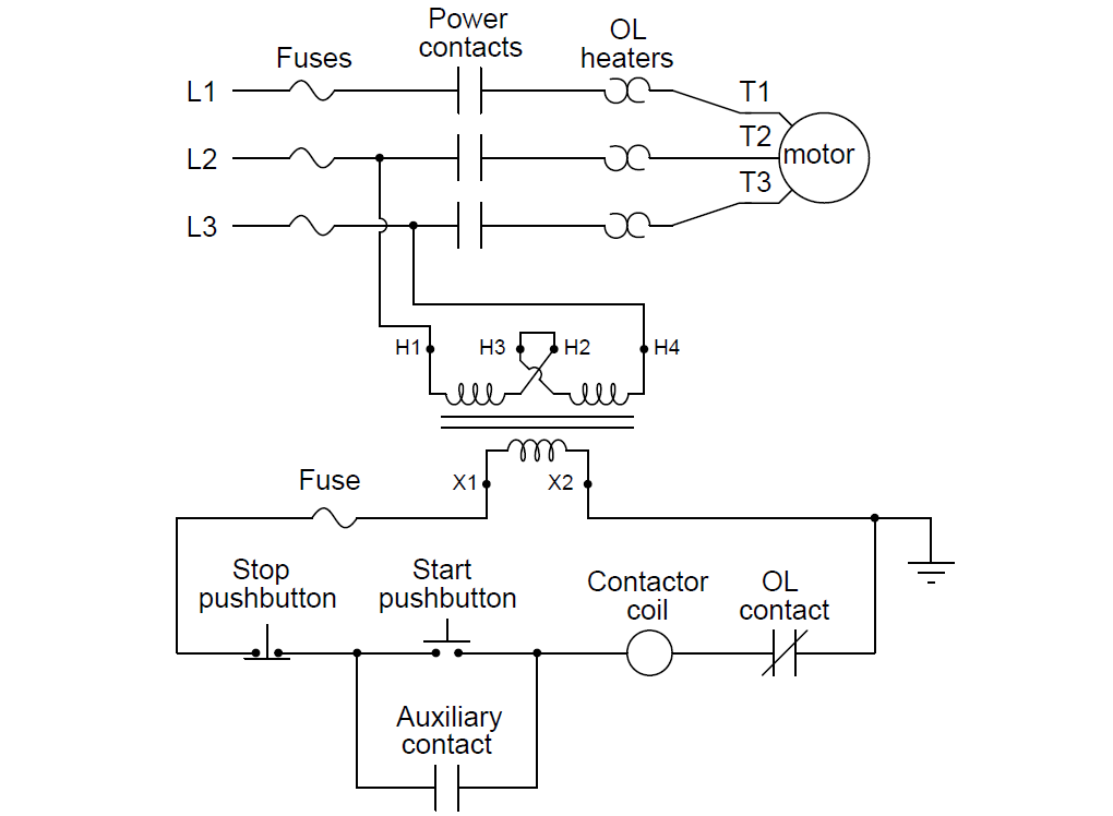
Motor Control Circuit Wiring Instrumentation Tools Note how a control power transformer steps down the 480 volt ac to provide 120 volt ac power for the contactor coil to operate on. furthermore, note how the overload (“ol”) contact is wired in series with the contactor coil so that a thermal overload event forces the contactor to de energize and thus interrupt power to the motor even if the control switch is still in the “on” position. Summary. motor contactor (or “starter”) coils are typically designated by the letter “m” in ladder logic diagrams. continuous motor operation with a momentary “start” switch is possible if a normally open “seal in” contact from the contactor is connected in parallel with the start switch, so that once the contactor is energized.

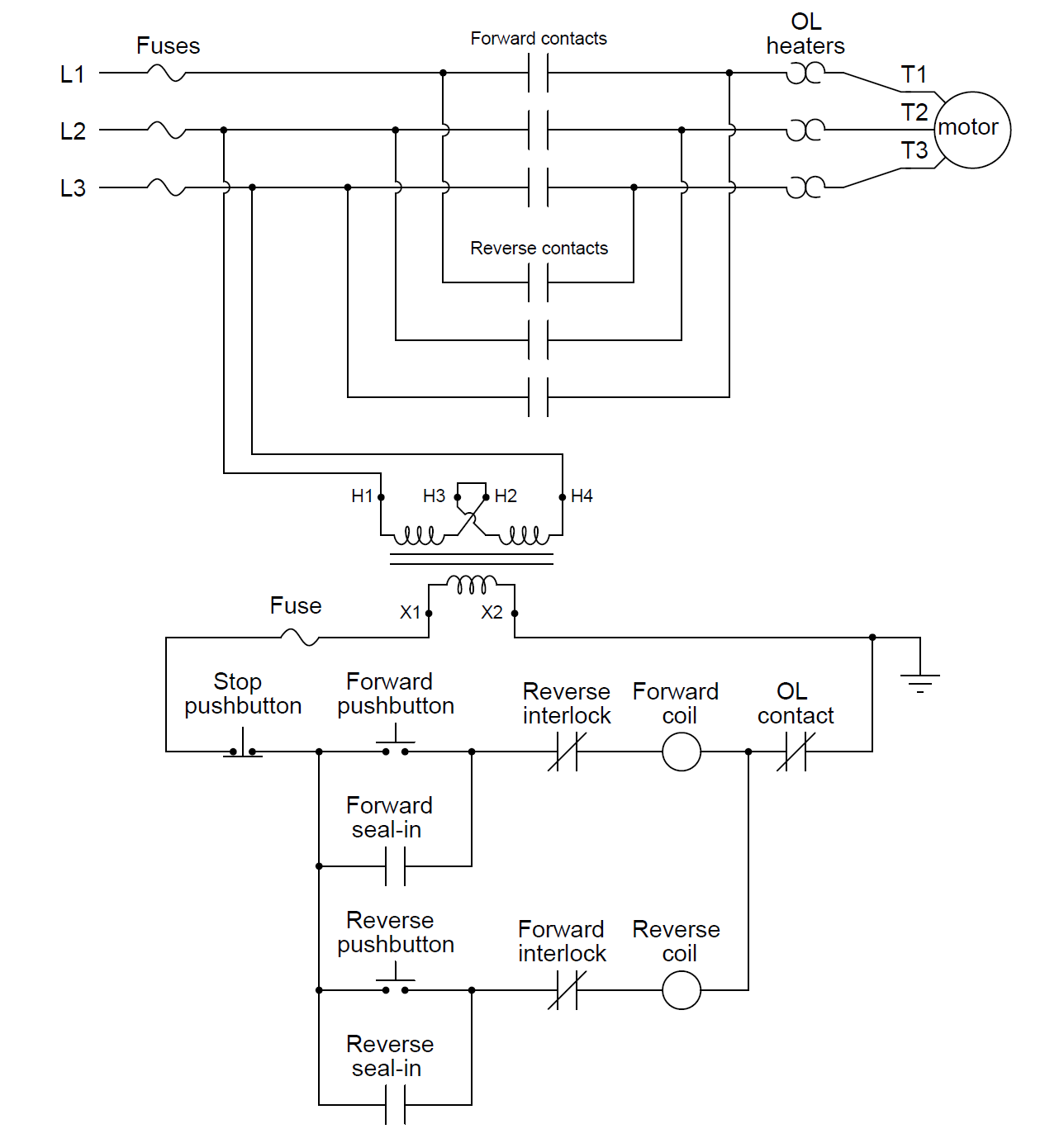
Motor Control Circuit Wiring Instrumentation Tools 6 ladder logic. motor control circuit. the interlock contacts installed in the previous section’s motor control circuit work fine (as discussed in previous article), but the motor will run only as long as each pushbutton switch is held down. if we wanted to keep the motor running even after the operator takes his or her hand off the control. Many different techniques exist for connecting electrical conductors together: twisting, soldering, crimping (using compression connectors), and clamping (either by the tension of a spring or under the compression of a screw) are popular examples. most industrial field wiring connections utilize a combination of compression style crimp “lugs. Required when a two wire control device is used. the bulletin 595 auxiliary contacts are designed as “a” and “b” on the wiring diagram. these contacts are easily. added to any allen bradley bulletin 500 starter sizes 0 through 4. when this system is used, the phase connections on all of the starters must be the same. Introduction to basic three phase motor control circuits. february 26, 2023 by david peterson. large motors require a circuit to turn on and off. this may be as simple as a single on off drum type switch or as elaborate as a vfd unit. learn about some common control circuit designs for typical three phase motor requirements.

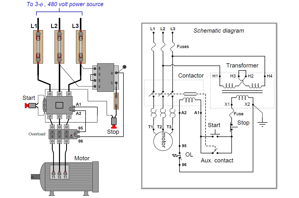
Motor Control Circuit Wiring Instrumentation Tools Required when a two wire control device is used. the bulletin 595 auxiliary contacts are designed as “a” and “b” on the wiring diagram. these contacts are easily. added to any allen bradley bulletin 500 starter sizes 0 through 4. when this system is used, the phase connections on all of the starters must be the same. Introduction to basic three phase motor control circuits. february 26, 2023 by david peterson. large motors require a circuit to turn on and off. this may be as simple as a single on off drum type switch or as elaborate as a vfd unit. learn about some common control circuit designs for typical three phase motor requirements. The control circuit is separate from the motor circuit. the control circuit may not be at the same voltage as the power circuit. when the voltage of the control and power circuits is the same, it is referred to as common control. if the volt ages are different, it is called separate control. figure 4. typical starter wiring diagram — three phase. A motor control circuit diagram typically includes various components such as motors, power supplies, control devices, relays, switches, and sensors. these components are interconnected through various electrical connections, such as wires and cables, to form a complete motor control system. the diagram provides a detailed illustration of how.

Comments are closed.