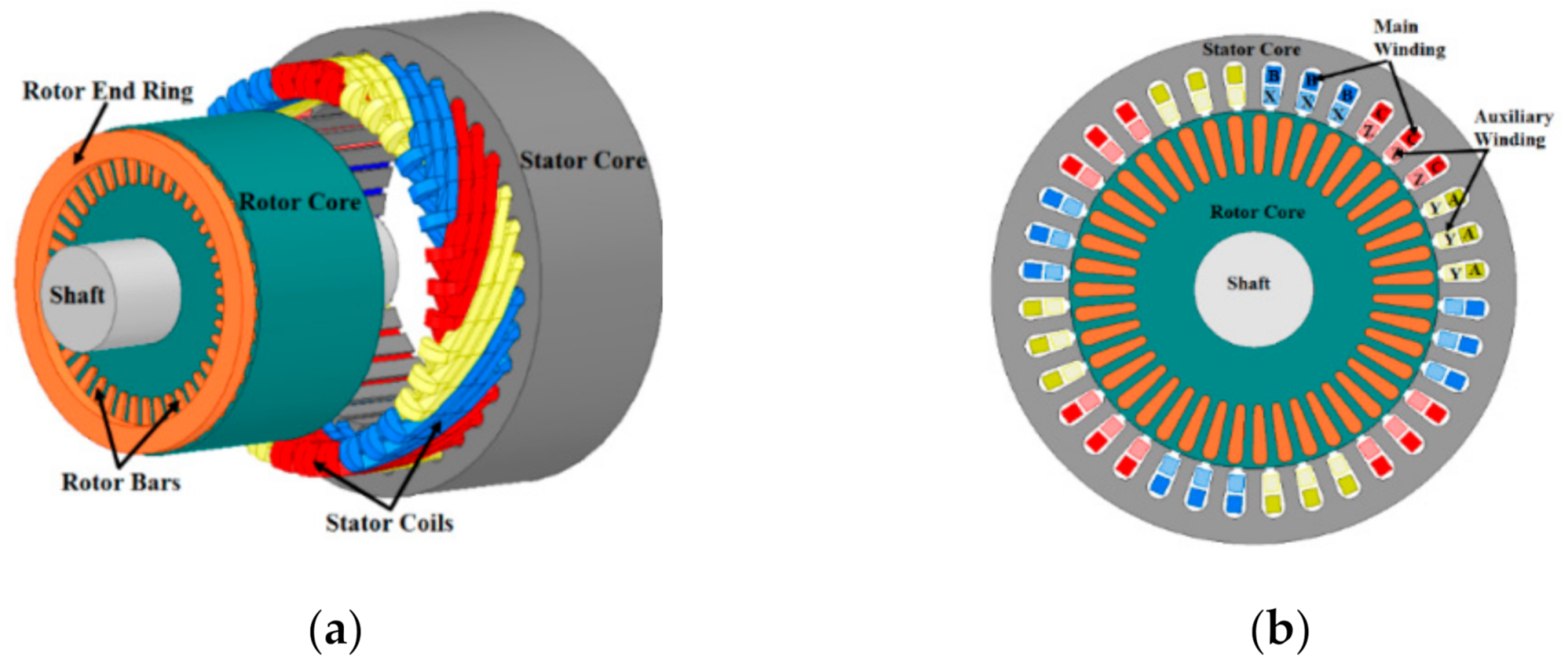
Motor Windings Diagram

Three Phase Electric Motor Winding Diagrams The original wiring diagram showed the proper arrangement of windings to create a larger wye system in which there are four equal windings between any two leads. figure 3. the connections required for high voltage wiring of a wye wound motor. in this wiring setup, there are 4 windings in series between any two line leads. One crucial component of a single phase motor is its winding diagram. this diagram illustrates the arrangement of the motor’s windings and provides insight into how the motor functions. understanding the winding diagram is essential for troubleshooting motor issues and for performing maintenance and repairs.
Single Phase Motor Windings Diagram Stator windings are stationary parts of an electrical motor that are supplied with an ac voltage which allows for current to flow. when a magnetic field occurs in the stator it drives the armature which causes the motor to rotate. a close up of a stator. the stator winding is among three parts that are found in the stator. This diagram illustrates the electrical connections between the stator windings of a motor, which are responsible for generating the rotating magnetic field necessary for motor operation. a 3 phase motor typically consists of three sets of windings, known as phases, labeled as a, b, and c. these windings are evenly distributed around the stator. The ac armature winding diagram is an important representation of the winding arrangement in an alternator or an electric motor. it helps to visualize the layout and connections of the winding coils, and it plays a crucial role in understanding the operation of the machine. 1. lap winding diagram: in a lap winding diagram, the winding coils are. A dc motor winding diagram is a graphical representation of the various components and connections within a dc motor. it is used to understand the layout and function of the winding system, which is crucial for proper motor operation and maintenance. dc motors consist of a stator (stationary part) and a rotor (moving part).

Single Phase Motor Windings Diagram The ac armature winding diagram is an important representation of the winding arrangement in an alternator or an electric motor. it helps to visualize the layout and connections of the winding coils, and it plays a crucial role in understanding the operation of the machine. 1. lap winding diagram: in a lap winding diagram, the winding coils are. A dc motor winding diagram is a graphical representation of the various components and connections within a dc motor. it is used to understand the layout and function of the winding system, which is crucial for proper motor operation and maintenance. dc motors consist of a stator (stationary part) and a rotor (moving part). The wiring diagram for a 3 phase motor shows how the motor’s three windings are connected to the power supply and control circuits. each winding corresponds to one phase of the electrical system, and the proper phasing and sequencing of these windings is crucial for the motor’s operation. the wiring diagram typically includes information. A dc motor winding diagram is a graphical representation that shows the arrangement and connections of the windings in a direct current (dc) motor. the diagram provides a visual guide for understanding the different coils and how they are connected in the motor. the winding diagram is essential for motor manufacturers, engineers, and.

3 Phase Motor Windings Diagram Vrogue Co The wiring diagram for a 3 phase motor shows how the motor’s three windings are connected to the power supply and control circuits. each winding corresponds to one phase of the electrical system, and the proper phasing and sequencing of these windings is crucial for the motor’s operation. the wiring diagram typically includes information. A dc motor winding diagram is a graphical representation that shows the arrangement and connections of the windings in a direct current (dc) motor. the diagram provides a visual guide for understanding the different coils and how they are connected in the motor. the winding diagram is essential for motor manufacturers, engineers, and.

Comments are closed.