Pneumatic Circuit Diagram Explanation

Pneumatic Circuit Diagram Explanation Directional air control valves are the building blocks of pneumatic control. pneumatic circuit symbols representing these valves provide detailed information about the valve they represent. symbols show the methods of actuation, the number of positions, the flow paths and the number of ports. here is a brief breakdown of how to read a symbol. In this beginner’s guide, we will break down the key components of pneumatic circuit diagrams and provide a step by step overview of how they function. at the core of any pneumatic system is the compressor, which generates compressed air that powers the entire system. understanding the principles behind compressors and how they fit into a.

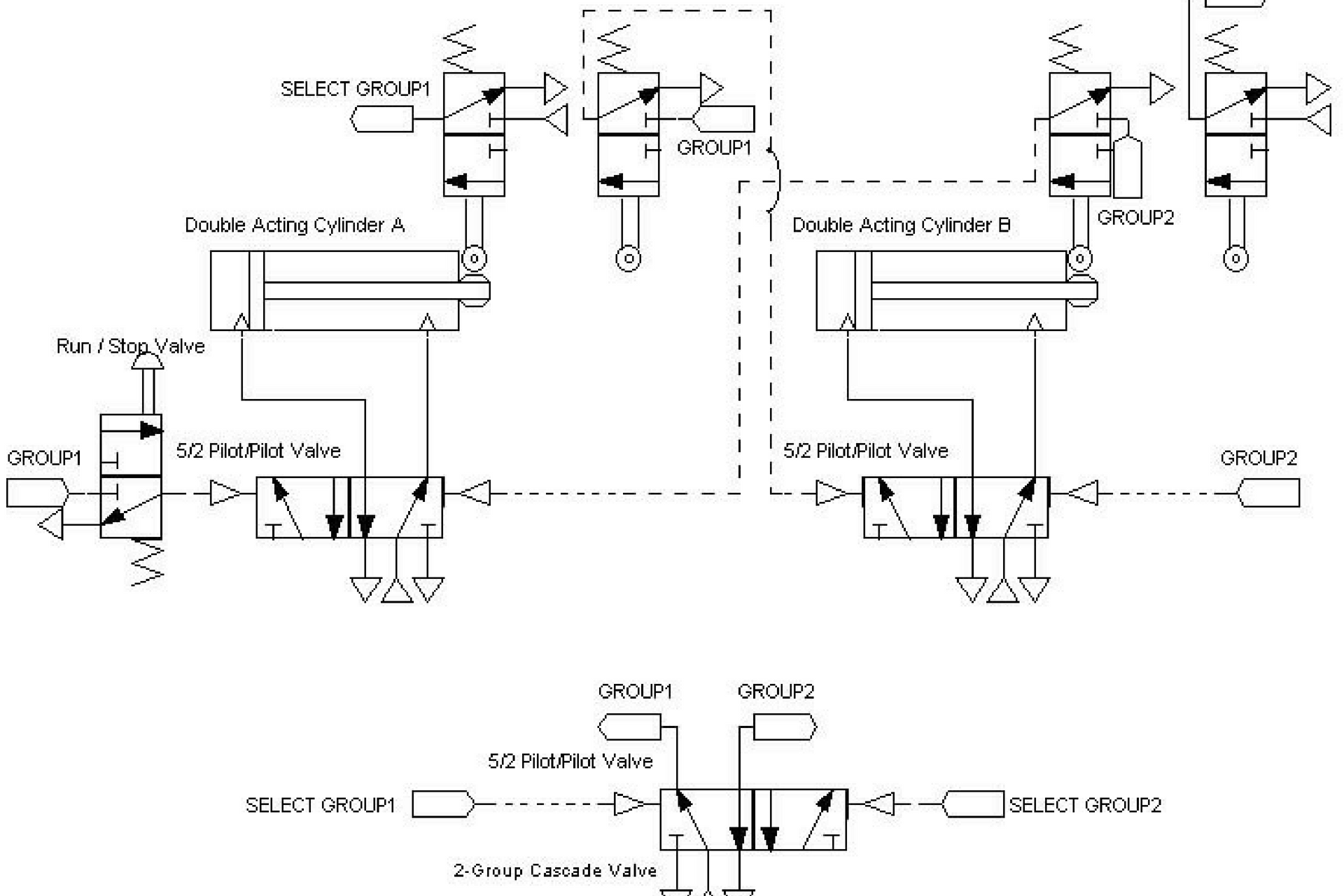
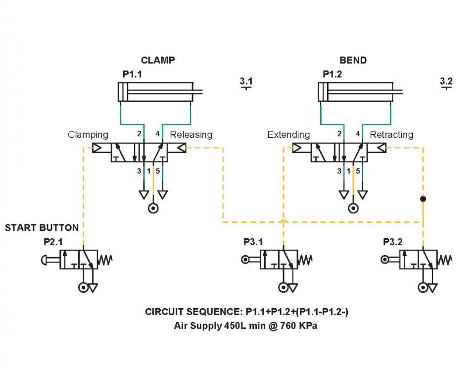
Pneumatic Circuit Diagram Pdf The 4 way, air piloted, directional control valve (vlv05) and the two 3 way roller actuated valves (vlv07and vlv08) are this circuit’s key pneumatic logic components. unlike electrical solenoids, they use air to control the 4 way valve’s spool position and are configured like limit switches with a mechanical arm. A pneumatic diagram, also known as a pneumatic circuit diagram or pneumatic schematic, is an essential tool for understanding and designing these systems. it visually represents the components, connections, and flow of compressed air or gases within a pneumatic system. at its core, a pneumatic diagram conveys information regarding the direction. These devices can be combined in many ways to provide simple and reliable machine control. this white paper examines pneumatic design best practices, and then presents four basic pneumatic circuits (table 1) commonly used in machine automation. while there are many variations, these pneumatic circuits combine basic pneumatic components to. In this article, we will explore some common examples of pneumatic circuit diagrams. 1. single acting cylinder circuit: this circuit diagram shows the operation of a single acting cylinder, which is a type of pneumatic actuator. it consists of a control valve, a cylinder, and a air supply.

Pneumatic Circuit Diagram Explanation These devices can be combined in many ways to provide simple and reliable machine control. this white paper examines pneumatic design best practices, and then presents four basic pneumatic circuits (table 1) commonly used in machine automation. while there are many variations, these pneumatic circuits combine basic pneumatic components to. In this article, we will explore some common examples of pneumatic circuit diagrams. 1. single acting cylinder circuit: this circuit diagram shows the operation of a single acting cylinder, which is a type of pneumatic actuator. it consists of a control valve, a cylinder, and a air supply. It is desired to move a 200lb load 12 inches at a rate of 20 cycles per minute. using a 2” bore cylinder, about 64 psi is required to move the load. adding 25% gives an operating pressure of 80 psi. at the desired cycle rate and using 1 4” od tubing (0.156” id), pressure losses in the tubing are about 1.5 psi per foot. In pneumatic circuit dia g rams, the components are arranged the way that the flow of energy always flows from the bottom up (as opposed to electrical schematics). thus the pressure source represents the first element, the actuator, the last element. in purely pneumatic circuits the processing of the input signals is also performed pneumatically.

Pneumatic Diagram Symbols It is desired to move a 200lb load 12 inches at a rate of 20 cycles per minute. using a 2” bore cylinder, about 64 psi is required to move the load. adding 25% gives an operating pressure of 80 psi. at the desired cycle rate and using 1 4” od tubing (0.156” id), pressure losses in the tubing are about 1.5 psi per foot. In pneumatic circuit dia g rams, the components are arranged the way that the flow of energy always flows from the bottom up (as opposed to electrical schematics). thus the pressure source represents the first element, the actuator, the last element. in purely pneumatic circuits the processing of the input signals is also performed pneumatically.

Comments are closed.