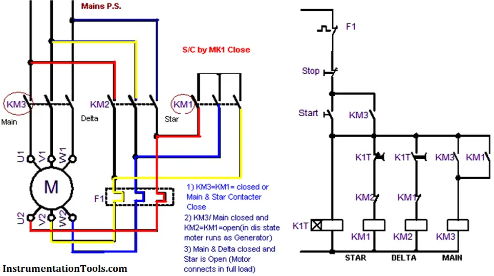
Relay Logic For Motor Operation And Ekts Simulation Part 3

Relay Logic For Motor Operation And Ekts Simulation Part 3 Youtube Use the like below to download ekts : dropbox home ibrahim%20 other dr%20ibrahim%20abdelsalam%20. Use the below link to download ekts software dropbox sh jbuyyazctem3z2p aacoy4pzvnrkjsfijd31wneda?dl=0.

Relay Logic For Motor Operation And Ekts Simulation Part 1 The relay coil symbol is used to indicate control relay or motor starter and sometimes even contactor or timer. 6. pilot lamp. the given symbol denotes pilot lamp or simply a bulb. they indicate the machine operation. relay logic circuit – examples and working. the working of a relay logic circuit can be explained through the given figures. Ekts (electrical control techniques simulator) is a simulator for designing electromechanical systems. design electromechanical systems using relays, time relays, buttons, motors, switches, basic mechanical systems, custom motor circuits using many motors. run simulator to check if designed system works. you can interact with ekts while it’s. Relay circuits and ladder diagrams. relay ladder circuits are the precursor to plc ladder logic. advanced machines and processes can be controlled by the interconnection of relays acting as logic gates much like a digital logic circuit. electromechanical relays may be connected together to perform logic and control functions, acting as logic. Ekts (electrical control techniques simulator) is used to design and analyse electric control systems. this subject studied at collages, universities and technical schools related with electric control systems. the main purpose of this simulator is to make contribution to the education of this subject. simulator is a program that behaves like a.

Relay Logic Wiring Diagram 4k Wallpapers Review Relay circuits and ladder diagrams. relay ladder circuits are the precursor to plc ladder logic. advanced machines and processes can be controlled by the interconnection of relays acting as logic gates much like a digital logic circuit. electromechanical relays may be connected together to perform logic and control functions, acting as logic. Ekts (electrical control techniques simulator) is used to design and analyse electric control systems. this subject studied at collages, universities and technical schools related with electric control systems. the main purpose of this simulator is to make contribution to the education of this subject. simulator is a program that behaves like a. A relay logic diagram is a graphical representation of a system or circuit that uses relays to control and manipulate electrical signals. it is used to design and understand the operation of relay based control systems. relay logic diagrams are commonly used in industrial automation and control applications. Motor control circuits. the interlock contacts installed in the previous section’s motor control circuit work fine, but the motor will run only as long as each push button switch is held down. if we wanted to keep the motor running even after the operator takes his or her hand off the control switch (es), we could change the circuit in a.

Star Delta Starter Circuit Diagram Download A relay logic diagram is a graphical representation of a system or circuit that uses relays to control and manipulate electrical signals. it is used to design and understand the operation of relay based control systems. relay logic diagrams are commonly used in industrial automation and control applications. Motor control circuits. the interlock contacts installed in the previous section’s motor control circuit work fine, but the motor will run only as long as each push button switch is held down. if we wanted to keep the motor running even after the operator takes his or her hand off the control switch (es), we could change the circuit in a.

Comments are closed.