Relay Logic Wiring Diagrams

Relay Logic Wiring Diagrams The given truth table can be implemented using the relay logic as follows – here, two normally close contacts are connected in series which means the pilot lamp will light up only if both the inputs are 0. if any one of the input becomes 1, that contact changes to normally open and hence the flow of current is interrupted, thereby causing the pilot l. Here, we will emulate the exact same high pressure alarm circuit using a siemens s7 1200 plc instead of a relay coil: wiring diagram: ladder logic program: suppose a fluid pressure of 36 psi is applied to the pressure switch. this is less than the switch’s trip setting of 50 psi, leaving the switch in its “normal” (closed) state.

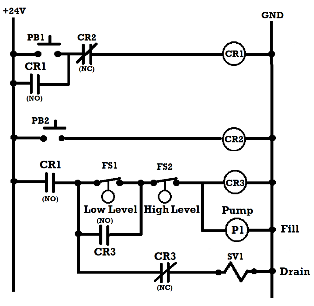
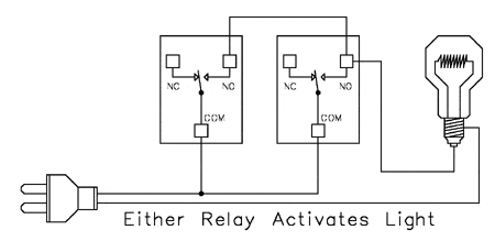
Relay Logic How To Connect Relays For Logical Switching Applications Example 2: traffic light control system. a traffic light control system is a common application of relay logic diagrams. it consists of several traffic lights at an intersection and a control system that regulates the timing and synchronization of these lights to ensure smooth traffic flow. components:. Use relay logic to control lights using relays in standard applications as well as 3 way switching application. our relay logic guide helps demonstrate the best ways to connect ncd relay controllers in real world control applications. the com (common) connection of a relay is the part of the relay that moves. when a relay is off, the common is. The relay logic circuit forms an electrical schematic diagram for the control of input and output devices. relay logic diagrams represent the physical interconnection of devices. each rung would have a unique identifying reference number and the individual wires on that rung would have wire numbers as a derivative of the rung number. Only two of the three diagrams shown use the same symbols to represent contacts, and all three use unique symbols to represent the coil. review: relays are used to switch high and low voltage circuits and provide logic combinations. single pole relays can be normally open (no), normally closed (nc), or both (double throw). these are called form.

Relay Logic Wiring Diagram The relay logic circuit forms an electrical schematic diagram for the control of input and output devices. relay logic diagrams represent the physical interconnection of devices. each rung would have a unique identifying reference number and the individual wires on that rung would have wire numbers as a derivative of the rung number. Only two of the three diagrams shown use the same symbols to represent contacts, and all three use unique symbols to represent the coil. review: relays are used to switch high and low voltage circuits and provide logic combinations. single pole relays can be normally open (no), normally closed (nc), or both (double throw). these are called form. Relay circuits. electromechanical relays may be connected together to perform logic and control functions, acting as logic elements much like digital gates (and, or, etc.). a very common form of schematic diagram showing the interconnection of relays to perform these functions is called a ladder diagram. in a “ladder” diagram, the two poles. Relay diagram symbols are graphical representations of various components and connections in an electrical relay circuit. these symbols are used to better understand and communicate the functionality of the circuit. they are commonly used in electrical engineering, automation, and control systems. one of the most important relay diagram symbols.

Comments are closed.