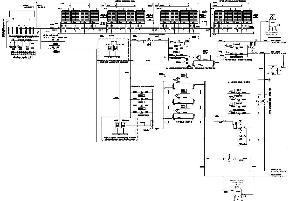
Schematic Diagram For Chiller System Cadbull

Schematic Diagram For Chiller System Cadbull You know what components make up the system, and what are involved in the design process and how they affect the outcome of the cooling system. let’s check out some chilled water diagrams and what are they. 1) 4000 ton water cooled centrifugal chiller. a standard chilled water system diagram consists of the chiller, cooling tower and pump. Chilled water schematic and condenser water schematic, how to read and understand the engineering drawings with real world examples, illustrations, animations and video tutorial. covering chillers, pump sets, ahus, risers, primary and secondary systems, cooling towers and bypass lines.

Schematic Diagram Of Chiller System Design In Detail Autocad 2d Drawing In a chilled water system, the entire air conditioner is installed on the roof or behind the building. it cools water to between 40 and 45 degrees fahrenheit (4.4 and 7.2 degrees celsius). the chilled water is then piped throughout the building and connected to air handlers. polyvinyl chloride (pvc) piping is used for chiller plant. The schematic diagram of a chiller system provides a visual representation of the different components and how they are interconnected. it helps engineers and technicians understand the system’s functionalities, troubleshoot any issues that may arise, and optimize its performance. the main components of a chiller system include a compressor. The basics of chillerspiping diagram schematic refrigeration drawing plumbing diagrams system commercial refrigerant installation electrical figure trane water wiring single basic systems guide hvac pipe design ~ all aboutchilled water piping diagram system plant primary holistic upgrading approach associated figure variable only. check details. A chiller system schematic diagram is a visual representation of the components and connections in a chiller system. this diagram helps in understanding the overall system design, including the refrigeration circuit, condenser, evaporator, and control components. an accurate and detailed chiller system schematic diagram is essential for troubleshooting, maintenance, and installation purposes.

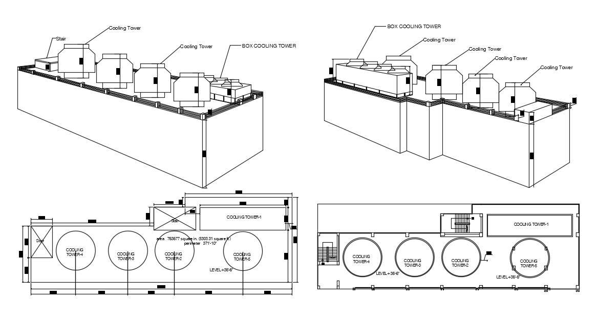
Building Chiller System Cad File Cadbull The basics of chillerspiping diagram schematic refrigeration drawing plumbing diagrams system commercial refrigerant installation electrical figure trane water wiring single basic systems guide hvac pipe design ~ all aboutchilled water piping diagram system plant primary holistic upgrading approach associated figure variable only. check details. A chiller system schematic diagram is a visual representation of the components and connections in a chiller system. this diagram helps in understanding the overall system design, including the refrigeration circuit, condenser, evaporator, and control components. an accurate and detailed chiller system schematic diagram is essential for troubleshooting, maintenance, and installation purposes. Chilled constant chilled chiller ahu flow cooled hvac return sistem extremum conditioner bagaimana sebenarnya seem chilled water schematic guide tw. chilled water schematic guide tw the engineering mindset. chilled schematic schematics chilled water systems chilled water system diagram. life is very short: e4101. Cooling tower schematic. tower cooling diagram schematic ac dwg system detail cadbull description valvec9 air heating cooling chiller hvac chilled conditioning refrigeration towers handling plumbing waterline 보드 선택 purgeschematic diagram of laboratory cooling tower.

Comments are closed.