Schematic Diagrams For Hvac Systems Modernize

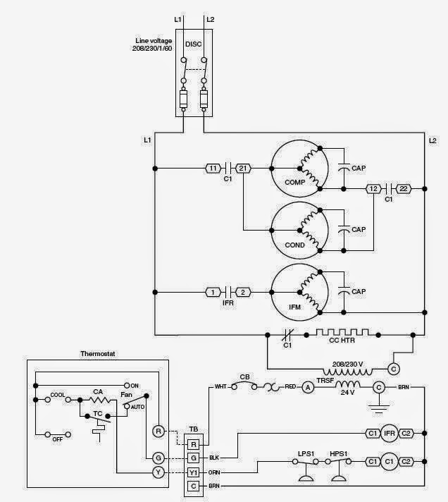
Schematic Diagrams For Hvac Systems Modernize Hvac system diagrams and schematics fall into three different categories: ladder, line, and installation diagrams. here’s how those break down. ladder diagrams. the ladder diagram is one of the easier ones to read. it lists the circuit connections and electrical wiring for the system. Reading hvac schematics. reading hvac schematics requires understanding symbols and their connections. start by identifying key components like compressors, heat exchangers, and fans. next, analyze how these parts connect through ducts and wiring. this helps in visualizing the system’s operation.

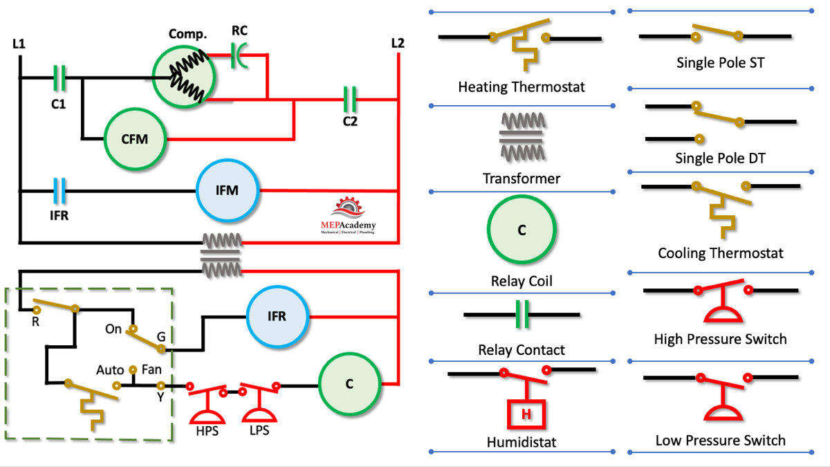
Schematic Diagrams For Hvac Systems Modernize Vrogue Co System schematics: produce in depth schematics to outline the hvac system and include details for ductwork routing, equipment placement, and control systems to ensure a clear representation of the system design. load calculations and efficiency: hvac drawings need to incorporate load calculations to accurately determine heating and cooling. Good hvac systems use the science of thermodynamics, heat transfer, and fluid mechanics to work. these are all fancy terms that mean the system will make the air warmer or cooler, creating a constant temperature inside your home. the science of cooling air means more than just blowing more air around and creating a current. Aircon, ac, and a c are common terms for air conditioning. it includes a fan to circulate the conditioned air within the room. the enclosed area can be a building or a vehicle. today, we’ll look at the definition, diagram, purposes, parts, types, and operating principle of an air conditioning system. so let’s start. A comprehensive hvac schematic symbols chart provides a key to deciphering the complex diagrams commonly used in hvac systems. by decoding these symbols, professionals can easily identify the different components and understand how they are interconnected in the system. the hvac schematic symbols chart typically includes symbols for various.

Hvac Unit Schematic Aircon, ac, and a c are common terms for air conditioning. it includes a fan to circulate the conditioned air within the room. the enclosed area can be a building or a vehicle. today, we’ll look at the definition, diagram, purposes, parts, types, and operating principle of an air conditioning system. so let’s start. A comprehensive hvac schematic symbols chart provides a key to deciphering the complex diagrams commonly used in hvac systems. by decoding these symbols, professionals can easily identify the different components and understand how they are interconnected in the system. the hvac schematic symbols chart typically includes symbols for various. An air conditioning system diagram is a visual representation of how an hvac (heating, ventilation, and air conditioning) system works. it depicts the various components of the system and how they interact to provide cool air and climate control in a building or vehicle. the diagram typically includes the following key components: compressor. The hvac schematic symbols chart includes a wide range of symbols that represent different types of equipment, such as motors, valves, dampers, pumps, and sensors. each symbol has a specific meaning, allowing professionals to quickly identify and troubleshoot issues within a system. for example, a motor symbol represents a motor used in an hvac.

Schematic Diagrams For Hvac Systems Modernize 53 Off An air conditioning system diagram is a visual representation of how an hvac (heating, ventilation, and air conditioning) system works. it depicts the various components of the system and how they interact to provide cool air and climate control in a building or vehicle. the diagram typically includes the following key components: compressor. The hvac schematic symbols chart includes a wide range of symbols that represent different types of equipment, such as motors, valves, dampers, pumps, and sensors. each symbol has a specific meaning, allowing professionals to quickly identify and troubleshoot issues within a system. for example, a motor symbol represents a motor used in an hvac.

Comments are closed.