Solved Analog Devices Real Analog Circuits 1 Chapter 4 Lab Chegg

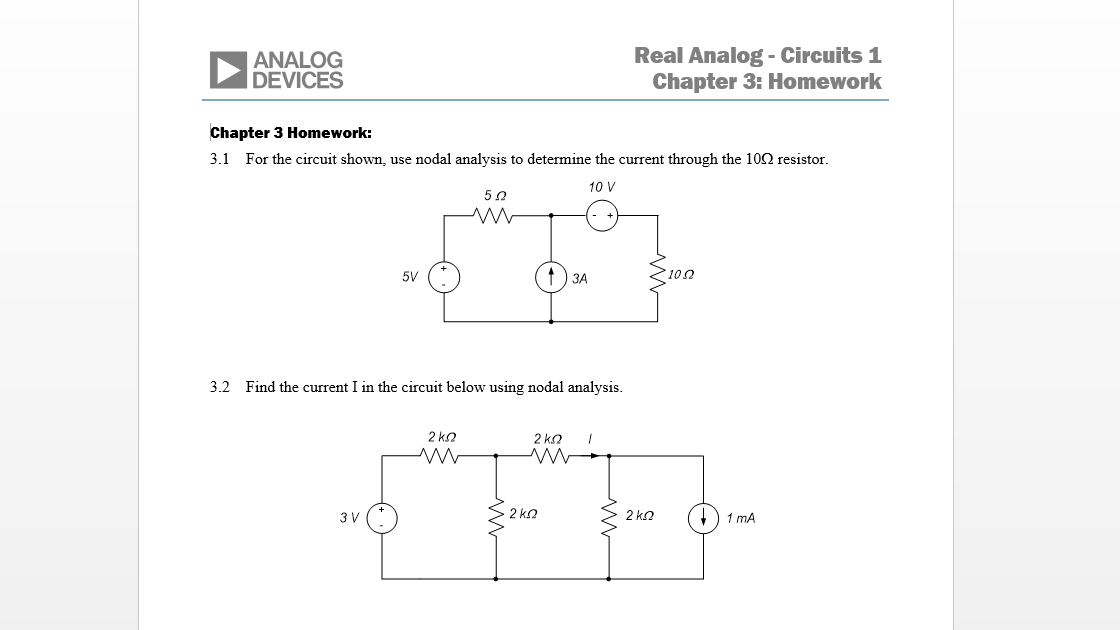
Solved Analog Devices Real Analog Circuits 1 Chapter 4 Lab Chegg Here’s the best way to solve it. analog devices real analog circuits 1 chapter 4: lab worksheets 4.5.1: thevenin's theorem (35 points total) in the space below, provide a sketch of the thevenin equivalent circuit you determined in the pre lab. label the thevenin resistance and the open circuit voltage on your sketch. (5 pts) i. 39% 4 rl 2. Analog devices real analog circuits 1 chapter 4: homework r 4 homework: 4. i) use superposition to determine the voltage v in the circuit below. the current u is an arbitrary value. 10 onc зо 60 6v 4.2 for the circuit of problem 1, determine an input output relationship between the current u and the voltage v. plot the relationship between.

Solved Analog Devices Real Analog Circuits 1 Chapter Real analog circuits 1 chapter 1: lab worksheets analog devices 1.2.1: power supplies, voltmeters, ammeters (25 points total) i. sketch the circuit below, indieate the voltages vc, e and the current i on your sketch. indicate on your sketch how the current and voltage measurements are being made. (2 pts) ode g dim mede c 2. what are the. Developed for university “circuits” classes by practicing engineers and experienced educators, real analog: circuits 1 is centered on a 12 chapter textbook and features: a 12 chapter textbook called real analog. exercises designed to reinforce textbook and lecture topics. homework assignments for every chapter. The problem can be solved very easily by adding some positive feedback to the operational amplifier or comparator circuit. this is provided by the addition of r 3 in the circuit in figure 4.14. the circuit is known as a schmitt trigger. resistor divider r 1 and r 2 set the comparison voltage at the non inverting input of the op amp. After completing this chapter, you should be able to: define signals and systems. represent systems in block diagram form. identify system inputs and outputs. write input output equations for systems. state the defining properties of linear systems. determine whether a system is linear.

Solved Analog Devices Real Analog Circuits 1 Chapter The problem can be solved very easily by adding some positive feedback to the operational amplifier or comparator circuit. this is provided by the addition of r 3 in the circuit in figure 4.14. the circuit is known as a schmitt trigger. resistor divider r 1 and r 2 set the comparison voltage at the non inverting input of the op amp. After completing this chapter, you should be able to: define signals and systems. represent systems in block diagram form. identify system inputs and outputs. write input output equations for systems. state the defining properties of linear systems. determine whether a system is linear. Real analog – circuits 1 lab project 4.3.1: superposition ©2012 digilent, inc. 2 general discussion: this lab assignment concerns the circuit shown in figure 1 below.use v to apply the 5v voltage source and w1 to apply the 3v source.we wish to determine thevoltage differencev. 5v 10kΩ 20kΩ 6.8kΩ 3v v 4.7kΩ figure 1. circuit. Real analog – circuits 1 lab project 4.5.1: thevenin's theorem ©2012 digilent, inc. 3 resistance and compare this voltage to your expectation based on the thevenin equivalent circuit from your pre lab. 4. build the thevenin equivalent circuit you determined in the pre lab. load the thevenin circuit with the resistor rlyou used in part 4.

Solved Analog Devices Real Analog Circuits 1 Chapter Real analog – circuits 1 lab project 4.3.1: superposition ©2012 digilent, inc. 2 general discussion: this lab assignment concerns the circuit shown in figure 1 below.use v to apply the 5v voltage source and w1 to apply the 3v source.we wish to determine thevoltage differencev. 5v 10kΩ 20kΩ 6.8kΩ 3v v 4.7kΩ figure 1. circuit. Real analog – circuits 1 lab project 4.5.1: thevenin's theorem ©2012 digilent, inc. 3 resistance and compare this voltage to your expectation based on the thevenin equivalent circuit from your pre lab. 4. build the thevenin equivalent circuit you determined in the pre lab. load the thevenin circuit with the resistor rlyou used in part 4.

Solved Real Analog Circuits 1 Chapter 1 Lab Workshee

Comments are closed.