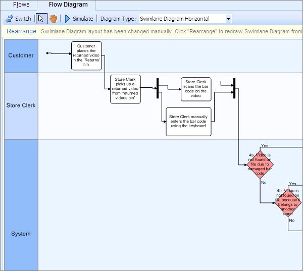
Solved Draw A Use Case Diagram Erd Diagram Swimlane D Vrogue Co

Solved Draw A Use Case Diagram Erd Diagram Swimlane D Vrogue Co Draw a. use case diagram. erd diagram. swimlane diagram . you are building a mobile application for xyz university, using the following project scopes, using a case diagram, a erd diagram, and a swimlane diagram. in scope: public access: all campus maps. news and event. admissions. bookstore. library (limited) general programs information. An er diagram depicting a charity employee with attributes like employee id, e name, e password, status, e task, e phone, and others is shown in the diagram below. data designers extensively use the er diagram model of charitable donations to convey their concepts. click to download and use this template.
Solved Draw A Use Case Diagram Erd Diagram Swimlane D Vrogue Co Summary. er model in dbms stands for an entity relationship model. the er model is a high level data model diagram. er diagrams are a visual tool which is helpful to represent the er model. er diagrams in dbms are blueprint of a database. entity relationship diagram dbms displays the relationships of entity set stored in a database. Er diagram or er model, is drawn to visually represent the relationships between entities in a database system. some benefits of drawing er diagrams for database design are: it helps in understanding the data relationships. er diagrams are like a blueprint for designing a database. helps in communicating about databases with database designers. Lucidchart is the leading er diagram tool. entity relationship diagrams (erd) are essential to modeling anything from simple to complex databases, but the shapes and notations used can be very confusing. this guide will help you to become an expert in er diagram notation, and you will be well on your way to model your own database! 4 minute read. A uml (unified modeling language) use case diagram is a visual representation of the interactions between actors (users or external systems) and a system under consideration. it depicts the functionality or behavior of a system from the user’s perspective. use case diagrams capture the functional requirements of a system and help to identify.
Solved Draw A Use Case Diagram Erd Diagram Swimlane D Vrogue Co Lucidchart is the leading er diagram tool. entity relationship diagrams (erd) are essential to modeling anything from simple to complex databases, but the shapes and notations used can be very confusing. this guide will help you to become an expert in er diagram notation, and you will be well on your way to model your own database! 4 minute read. A uml (unified modeling language) use case diagram is a visual representation of the interactions between actors (users or external systems) and a system under consideration. it depicts the functionality or behavior of a system from the user’s perspective. use case diagrams capture the functional requirements of a system and help to identify. The choice between class diagrams and erds depends on the project’s focus and requirements. class diagrams suit object oriented software development and architectural modeling, while erds are essential for database design and data modeling tasks. both diagram types play crucial roles in different phases of software development and design. An entity relationship diagram (erd) is a visual representation of different entities within a system and how they relate to each other. it is a tool used to design and model relational databases, and shows the logical structure of the database. er diagrams use symbols to represent entities, attributes, and relationships, which help to.

Comments are closed.