Sony Car Stereo Circuit Diagram

Sony Car Stereo Circuit Diagram Understanding the basics of sony stereo wiring. when it comes to installing or upgrading a car stereo system, it is crucial to understand the basics of sony stereo wiring. sony is a renowned brand known for producing high quality audio equipment, and their stereo wiring diagram can be a valuable resource. Sony radio wiring harness diagrams. we’ve recently published radio wiring guides for brands such as pioneer, kenwood, alpine, etc. so in this post, we’ll talk about sony radios’ wiring diagrams. the radios we’ve used as examples are mex n5300bt and xav7000. sony mex n5300bt wiring diagram and color codes.

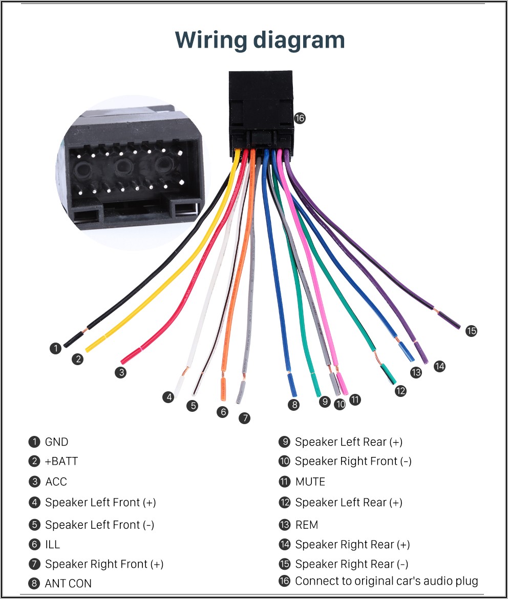
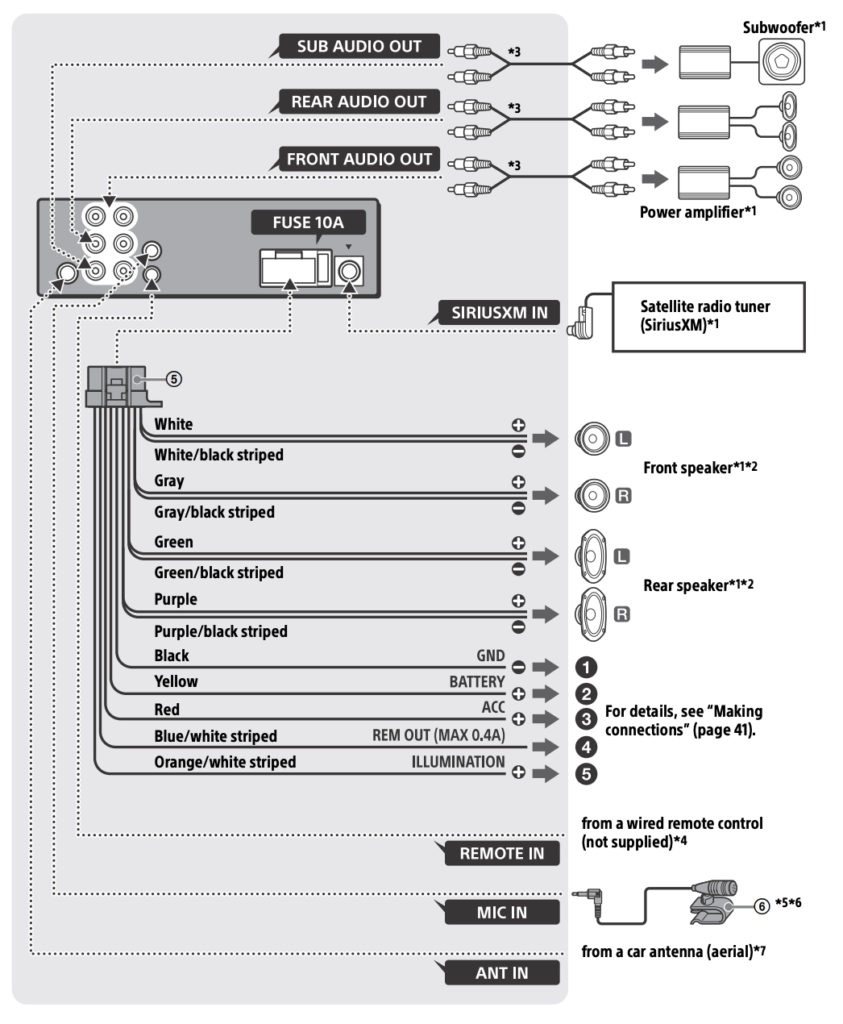
Sony Car Stereo Wiring Diagram And Color Codes 16 Pin Getting wiring diagrams and color codes for your sony car stereo is easy with these 16 pin diagrams and color codes. please find attached wiring diagrams for single din units sony dsx a415bt, sony xplod mex bt3900u, and sony xav ax1000. Important: if additional installation procedures or information is needed, contact a qualified car stereo installer. pin number. wire color. function. 1. white. left front positive. 2. green. A sony car stereo wiring diagram includes the following components: a main power cable connecting the head unit to the battery. a ground cable, which connects the head unit to the vehicle chassis. one or more speaker cables, connecting each speaker to the head unit. one or more rca cables, which connect the head unit to any external amplifiers. Place the sony head unit into the designated slot in your vehicle’s dashboard and secure it using a socket wrench set. make sure it is firmly in place. 7. reconnect the negative battery terminal. after completing the wiring and mounting process, reconnect the negative battery terminal to restore power to your vehicle.

Wiring Diagrams For Sony Car Stereo Circuit Diagram A sony car stereo wiring diagram includes the following components: a main power cable connecting the head unit to the battery. a ground cable, which connects the head unit to the vehicle chassis. one or more speaker cables, connecting each speaker to the head unit. one or more rca cables, which connect the head unit to any external amplifiers. Place the sony head unit into the designated slot in your vehicle’s dashboard and secure it using a socket wrench set. make sure it is firmly in place. 7. reconnect the negative battery terminal. after completing the wiring and mounting process, reconnect the negative battery terminal to restore power to your vehicle. Sony xav ax1000 (single din) wiring color codes guide. let's explore some additional wire colors that play crucial roles in your car stereo system's functionality: orange white striped: the orange white striped wire carries the illumination signal. connecting this wire allows you to control the brightness of your car stereo's display and buttons. Connect the wiring harness adapter. take the wiring harness adapter specific to your car model and connect its wires to the corresponding wires on the sony mex n5100bt stereo. ensure that the connections are secure by using crimp connectors or soldering. 5. connect the power wires.

Sony Wiring Diagram Car Stereo Sony xav ax1000 (single din) wiring color codes guide. let's explore some additional wire colors that play crucial roles in your car stereo system's functionality: orange white striped: the orange white striped wire carries the illumination signal. connecting this wire allows you to control the brightness of your car stereo's display and buttons. Connect the wiring harness adapter. take the wiring harness adapter specific to your car model and connect its wires to the corresponding wires on the sony mex n5100bt stereo. ensure that the connections are secure by using crimp connectors or soldering. 5. connect the power wires.

Comments are closed.