Start Stop Circuit What They Are Where They Are Used And How To Wire

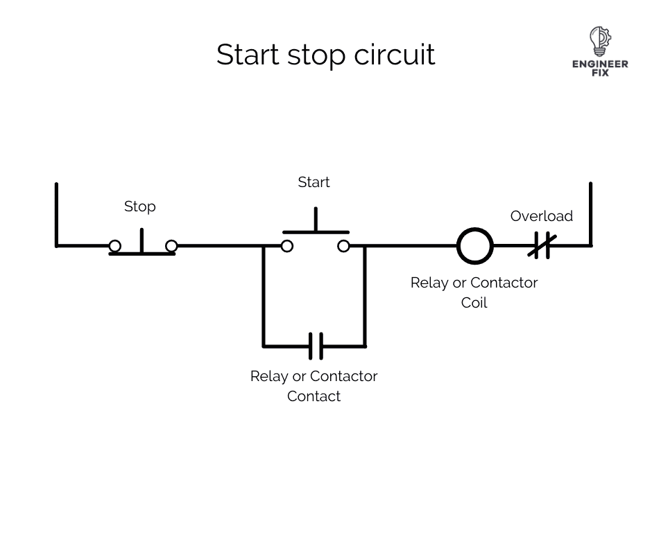
Start Stop Circuit What They Are Where They Are Used And How To Wire Start stop circuit with start button pressed. when we press the start button it allows current to flow through the circuit and activate the relay or contactor coil. an example of where a contactor would be used is when controlling a motor. when the coil of the contactor is activated it allows current to flow to the motor, this will run the motor. A start stop wiring diagram is a schematic representation of the electrical connections and components used in a basic start stop circuit. this type of wiring diagram is commonly used in industrial applications to control the operation of motors or other electrical devices. the start stop circuit is a simple control circuit that allows for the.

Start Stop Circuit Diagram Here are some guidelines to consider: 1. use clearly labeled wires: labeling the wires in your motor control circuit can greatly simplify troubleshooting and maintenance. use clear and descriptive labels for each wire, such as “power supply,” “start button,” “stop button,” “motor,” etc. 2. use color coded wires:. A start stop circuit is an electrical circuit that controls the operation of machines or systems containing electrical motors and control circuits. it is designed to start or stop motors, ladder logic networks, electrical equipment, or components. the circuit comprises several electrical components and wiring, including contacts, relays or. The start stop switch consists of two positions: a “start” position and a “stop” position. when the switch is in the “start” position, it completes the electrical circuit and allows the current to flow to the device or circuit. this results in the activation or start of the machine or system. on the other hand, when the switch is in. A start stop motor diagram is a visual representation of the wiring and connections required to operate a motor with a start stop control circuit. this type of circuit is commonly used in industrial settings to control the operation of motorized equipment such as pumps, fans, and conveyors. the diagram typically consists of several components.
Start Stop Circuits Wiring Diagrams And Motor Control Schematics The start stop switch consists of two positions: a “start” position and a “stop” position. when the switch is in the “start” position, it completes the electrical circuit and allows the current to flow to the device or circuit. this results in the activation or start of the machine or system. on the other hand, when the switch is in. A start stop motor diagram is a visual representation of the wiring and connections required to operate a motor with a start stop control circuit. this type of circuit is commonly used in industrial settings to control the operation of motorized equipment such as pumps, fans, and conveyors. the diagram typically consists of several components. Step 4: connect the power source. first, connect the power source to the common terminal (com) on the start stop switch. ensure that the conductors are securely attached using appropriate wire connectors or screws. use a voltage tester to verify the presence of electrical current. It provides the necessary power and control to start and stop the motor. the motor starter consists of several key components that work together to ensure the smooth and safe operation of the motor. 1. contactor: the contactor is a device that allows or interrupts the flow of electrical current to the motor.
Start Stop Circuits Wiring Diagrams And Motor Control Schematics Step 4: connect the power source. first, connect the power source to the common terminal (com) on the start stop switch. ensure that the conductors are securely attached using appropriate wire connectors or screws. use a voltage tester to verify the presence of electrical current. It provides the necessary power and control to start and stop the motor. the motor starter consists of several key components that work together to ensure the smooth and safe operation of the motor. 1. contactor: the contactor is a device that allows or interrupts the flow of electrical current to the motor.

Comments are closed.