Ternary Phase Diagrams Explained

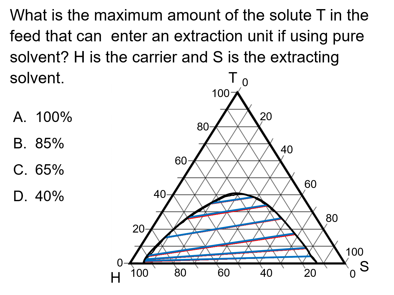
Ternary Phase Diagrams Conceptests Learncheme A ternary phase diagram consists of three axes, each representing the composition of one component in the system. the diagram is divided into regions that represent different phases, such as solid solutions, compounds, and eutectic mixtures. the boundaries between these regions are called phase boundaries or phase lines. Note that the relationship among the concentrations of the components is more complex than that of binary systems. figure 5.4.1 5.4. 1: three component triangular representation (i.e. 'blank graph paper' for a ternary diagram phase diagram), with axis labels perpendicular to each plotting axis to facilitate plotting and comprehension.

How To Use A Ternary Plot вђ Geology Is The Way Ternary phase diagrams are used to represent all possible mixtures of three solvents [1]; they are described in chapter 3. here, we shall indicate how they should be used to minimize the solvent consumption. figure 2.1 (top) shows the methanol–chloroform–water ternary phase diagram with the tie lines in the biphasic domain. Ternary diagrams allow geoscientists to represent the relative proportions of three components in a system. in order to plot data on a ternary diagram, the components are normalized to 100% (i.e., you must determine the proportions of each component relative only to the other components represented on the diagram; more on that later). ternary. Understanding phase diagrams – v.b. john. ternary phase diagram books by d.r.f. west – there are several. diagram. c. ternary grid. space diagram. usually have elements at the corners as the constituents, but can have compounds: for diagrams where there is a major component, e.g. fe in fe c cr, use a right angled triangle → ← for. In this lecture we discuss how to use and interpret isothermal cuts of ternary phase diagrams. this lecture was designed and delivered by patrick woodward fo.

Ternary Phase Diagrams 101 Diagrams Understanding phase diagrams – v.b. john. ternary phase diagram books by d.r.f. west – there are several. diagram. c. ternary grid. space diagram. usually have elements at the corners as the constituents, but can have compounds: for diagrams where there is a major component, e.g. fe in fe c cr, use a right angled triangle → ← for. In this lecture we discuss how to use and interpret isothermal cuts of ternary phase diagrams. this lecture was designed and delivered by patrick woodward fo. This teaching and learning package (tlp) introduces basic concepts of ternary phase diagrams. aims. before you start. introduction. representing ternary phase diagrams. sections through ternary phase diagrams. tie lines and tie triangles. applying the gibbs phase rule to ternary systems. solidification of ternary alloys – complete solid solution. This is because c is precipitating and the liquid is becoming impoverished in c and enriched in the components a b. at a temperature of about 820°, point l in figure 3, we can determine the relative proportion of crystals and liquid. % crystals = a (a b)*100. % liquid = b (a b)*100. with further cooling, the path of the liquid composition.

Comments are closed.