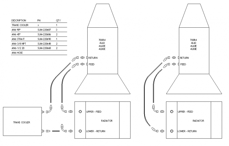
Th350 Cooling Line Diagram
Technical Routing Lines From Th350 To Radiator The H A M B Powered by wordpress and hitmag. view turbo 350 (th350) transmission cooler line diagrams and cooler flow path that route to the radiator and to an external transmission cooler. May 11, 2023 alex gearhart. turbo 350 transmission cooler lines diagrams show the flow of fluid through the transmission cooling system. the diagram will usually have a schematic that shows all of the components in the system, including the lines going to and from each component. there are two types of coolers: external and internal.
Th350 Cooling Lines Diagram Make sure that you use the correct fittings, with either inverted flare, barb or compression fitting. 1 4 nps with parallel thread and washer for inverted flare and double flared hard line with tube nut (1 2 20 for 5 16 tube or 7 16 24 for 1 4 tube). The cooler lines help to circulate the fluid through the transmission cooler, which is typically located in the radiator or a separate transmission cooler. this helps to dissipate the heat and keep the fluid at an optimal temperature. understanding the th350 transmission cooler lines diagram is crucial for proper installation and maintenance. Bottom line goes to upper rad port. gravity will return atf to bottom port of rad. an extra trans cooler. all you need is a little 7" x 9" or 8" x 11" thin cooler out in front of the rad or in front of the a c condenser. if you get a 3 4" thick unit it will not interfere with an open hood in the front. Here is a breakdown of the different components typically shown in a turbo 350 transmission cooler lines diagram: transmission: this is the main component of the transmission cooling system. it is responsible for transmitting power from the engine to the wheels.

Diagram Th350 Cooler Lines In And Out Bottom line goes to upper rad port. gravity will return atf to bottom port of rad. an extra trans cooler. all you need is a little 7" x 9" or 8" x 11" thin cooler out in front of the rad or in front of the a c condenser. if you get a 3 4" thick unit it will not interfere with an open hood in the front. Here is a breakdown of the different components typically shown in a turbo 350 transmission cooler lines diagram: transmission: this is the main component of the transmission cooling system. it is responsible for transmitting power from the engine to the wheels. Th350, th250. fitting location thread size flow direction. upper ¼" pipe return in. lower ¼" pipe cooler feed out. th400. fitting location thread size flow direction. upper ¼" pipe return in. lower ¼" pipe cooler feed out. 700r4 4l60 4l60e 4l65e. Replacing the kinked and leaking steel transmission cooler lines with nicopp lines. if you haven't started using nicop over steel, you are missing out. we al.

Th350 Cooling Line Diagram Th350, th250. fitting location thread size flow direction. upper ¼" pipe return in. lower ¼" pipe cooler feed out. th400. fitting location thread size flow direction. upper ¼" pipe return in. lower ¼" pipe cooler feed out. 700r4 4l60 4l60e 4l65e. Replacing the kinked and leaking steel transmission cooler lines with nicopp lines. if you haven't started using nicop over steel, you are missing out. we al.

Comments are closed.