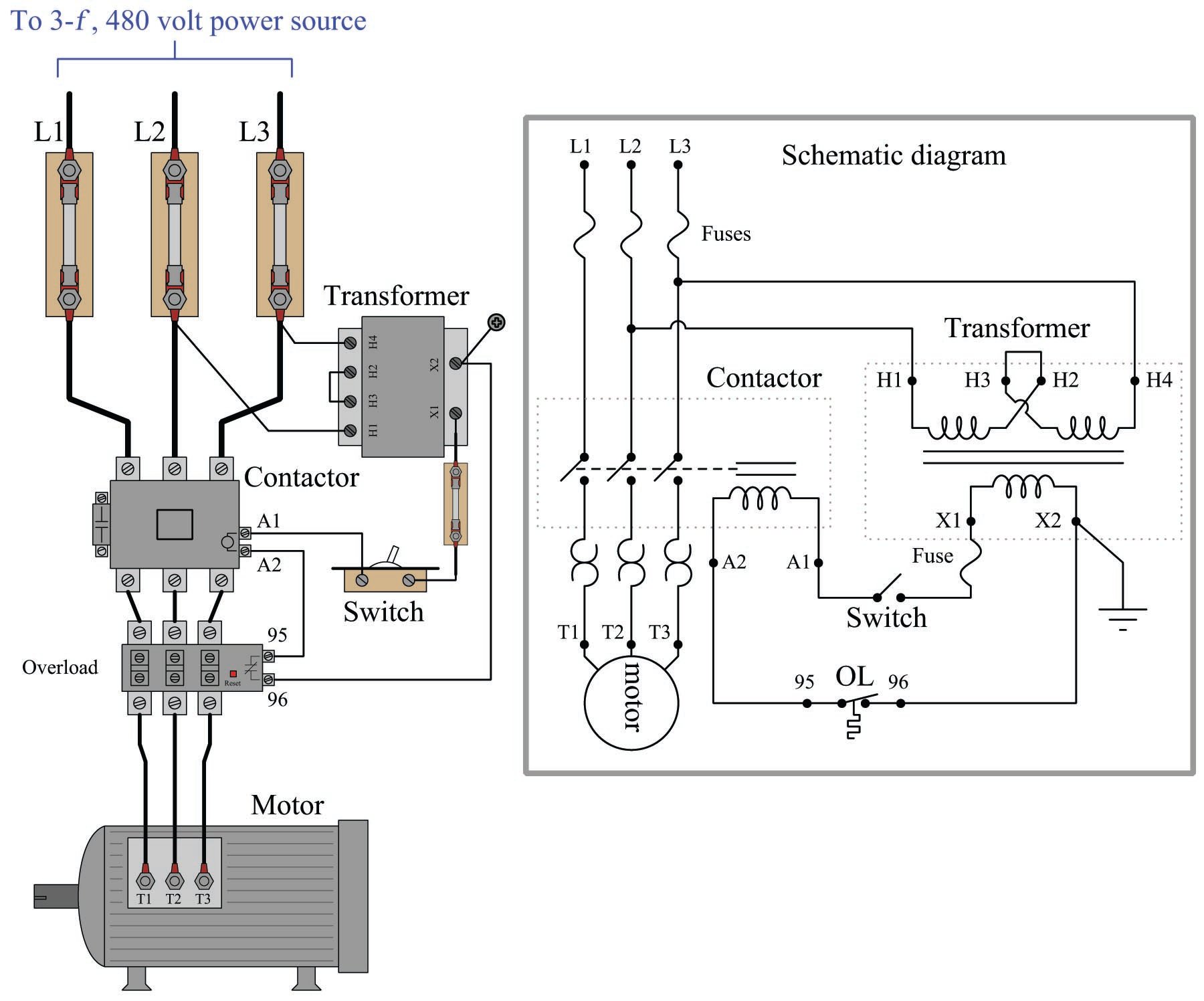
Three Phase Motor Control Circuit Diagram

Schematic Diagram Of Three Phase Motor Introduction to basic three phase motor control circuits. february 26, 2023 by david peterson. large motors require a circuit to turn on and off. this may be as simple as a single on off drum type switch or as elaborate as a vfd unit. learn about some common control circuit designs for typical three phase motor requirements. The wiring diagram for a 3 phase motor shows how the motor’s three windings are connected to the power supply and control circuits. each winding corresponds to one phase of the electrical system, and the proper phasing and sequencing of these windings is crucial for the motor’s operation. the wiring diagram typically includes information.

3 Phase Motor Control Circuit Diagram Three phase motor connection star delta without timer – power & control diagrams. three phase motor connection star delta (y Δ) reverse forward with – timer power & control diagram. starting & stopping of 3 phase motor from more than one place power & control diagrams. control 3 phase motor from more than two buttons – power & control. The control circuit is separate from the motor circuit. the control circuit may not be at the same voltage as the power circuit. when the voltage of the control and power circuits is the same, it is referred to as common control. if the volt ages are different, it is called separate control. figure 4. typical starter wiring diagram — three phase. To achieve two speed, one direction control of a three phase motor using contactors, follow these steps: power & control circuit diagram. draw a schematic diagram and wire the power and control circuit as shown in the figures below. this circuit will consist of a power supply, a low speed contactor (k1), high speed contactors (k2 and k3), a. The contactor should have three main terminals for the three phase power supply (l1, l2 & l3) and three auxiliary contacts for control circuits. install a relay with two sets of contacts, one for forward operation and the other for reverse operation. connect the relay to the control circuit of the contactor. connect the three phase power supply.

Three Phase Motor Control Circuit Diagram Pdf To achieve two speed, one direction control of a three phase motor using contactors, follow these steps: power & control circuit diagram. draw a schematic diagram and wire the power and control circuit as shown in the figures below. this circuit will consist of a power supply, a low speed contactor (k1), high speed contactors (k2 and k3), a. The contactor should have three main terminals for the three phase power supply (l1, l2 & l3) and three auxiliary contacts for control circuits. install a relay with two sets of contacts, one for forward operation and the other for reverse operation. connect the relay to the control circuit of the contactor. connect the three phase power supply. In a three phase motor diagram, each phase is represented by a different colored wire – typically red, yellow, and blue. these wires are connected to the motor’s power supply, which supplies alternating current (ac) in three separate phases. the diagram also shows the motor’s control circuit, which includes components such as switches. Understanding its circuit diagram can help in troubleshooting and maintaining such motors. the three phase motor circuit diagram typically consists of three main components: the power supply, the motor, and the control circuit. the power supply provides three phase ac power, which is then fed to the motor. the motor consists of three windings.

Comments are closed.