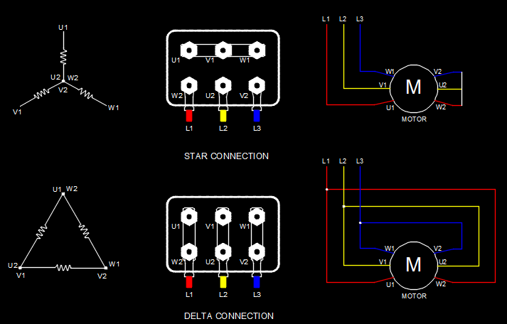
Three Phase Motor Wiring Connection

How To Proper Connection 3 Phase Motor аґ аґ 3 Phase Motor A 3 phase motor is a type of motor that operates with three separate phases of electrical power, and its wiring diagram depicts the connections between these phases and the motor itself. the 3 phase wiring diagram for motors typically includes information such as the voltage and current ratings, the type of motor (e.g., induction motor or synchronous motor), and the connection details. To wire a 3 phase motor, first, identify the wires and check the wiring diagram on the motor. 6 wires are from the motor, 1 for grounding if provided, and 3 (l1 3) from the power supply. choose one of the two configurations (star or delta) and connect the wires to the terminals accordingly. then, connect the ground wire to the grounding.

Electric Motor Wiring Connection Wiring a three phase motor is an essential step in industrial and commercial electrical installations. three phase motors are commonly used in various applications, such as pumps, fans, compressors, and more. these motors provide a higher power output compared to their single phase counterparts, making them ideal for heavy duty operations. The most common type of three phase motor is that which has nine labeled (and often colored) wires coming out of the box on the side. there are many motors with more or fewer wires, but nine is the most common. these nine wire motors may be internally connected with either a wye (star) or a delta configuration, established by the manufacturer. The three phase motor connection diagram typically consists of three sets of wires, labeled as “t1”, “t2”, and “t3”. these wires correspond to the three phases of the electrical system and are used to supply power to the motor. in addition to these three wires, there may also be other wires labeled with letters such as “u”, “v. Each phase winding carries alternating current that is shifted by 120 degrees from the other phases. the 3 phase motor winding connection diagram depicts the way these winding ends are connected to create the three phase electrical system. there are two common types of connections used in three phase motor windings: star (y) and delta (Δ).

Three Phase Motor Connection The three phase motor connection diagram typically consists of three sets of wires, labeled as “t1”, “t2”, and “t3”. these wires correspond to the three phases of the electrical system and are used to supply power to the motor. in addition to these three wires, there may also be other wires labeled with letters such as “u”, “v. Each phase winding carries alternating current that is shifted by 120 degrees from the other phases. the 3 phase motor winding connection diagram depicts the way these winding ends are connected to create the three phase electrical system. there are two common types of connections used in three phase motor windings: star (y) and delta (Δ). In a three phase motor, the star connection is one of the common ways to wire the motor. in this connection, the three ends of the motor windings are connected together to form a star shape. the three other ends, also known as the line terminals, are connected to the three phase power supply. when the motor is running in star connection, the. Step 1: gather the necessary tools and equipment. before you begin wiring a 3 phase motor, it is important to gather all the necessary tools and equipment. having the right tools at hand will help ensure a smooth and efficient wiring process. here are some of the essential tools and equipment you will need: circuit tester: this tool is used to.

3 Phase Motor Wiring Connection In a three phase motor, the star connection is one of the common ways to wire the motor. in this connection, the three ends of the motor windings are connected together to form a star shape. the three other ends, also known as the line terminals, are connected to the three phase power supply. when the motor is running in star connection, the. Step 1: gather the necessary tools and equipment. before you begin wiring a 3 phase motor, it is important to gather all the necessary tools and equipment. having the right tools at hand will help ensure a smooth and efficient wiring process. here are some of the essential tools and equipment you will need: circuit tester: this tool is used to.

Three Phase Induction Motor Connection вђў Designs Cad

Comments are closed.