Water Cooled Chiller Diagram Hvac Investigators

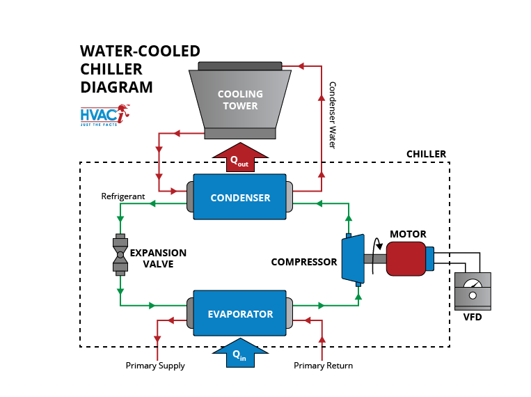
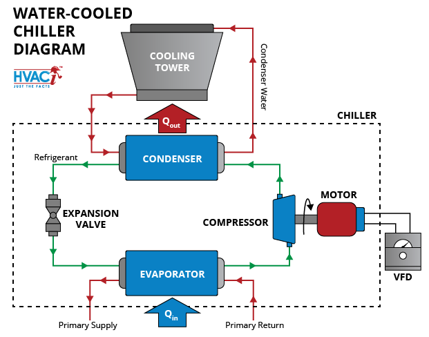
Water Cooled Chiller Diagram Hvac Investigators The term “water cooled” is referring to the condenser side of the chiller. if the heat rejection is via water, then the chiller is water cooled. see my post on the other types of chillers in hvac. the chiller itself is a giant air conditioner. the chilled water pump pushes the water through the evaporator of the chiller thereby cooling the. In a chilled water system to remove heat from zone or process loads. this system comprises one or more chillers, cooling tower(s), condenser water pumps, chilled water pumps, and load terminals served by control valves. fixed or variable speed compressors provide cooling, while flow rates are optimized for a combination of efficiency and cost.

The Basics Of Chillers Hvac Investigators Chillers use the refrigeration cycle to remove heat from water. a chilled water system’s refrigeration cycle works by removing heat from chilled water in the evaporator of the chiller. the compressor is what drives the entire process. it also uses the most energy in a chilled water system. in the condenser of the chiller, the heat is. Chilled water schematic and condenser water schematic, how to read and understand the engineering drawings with real world examples, illustrations, animations and video tutorial. covering chillers, pump sets, ahus, risers, primary and secondary systems, cooling towers and bypass lines. A chiller cooling system diagram is a valuable tool for understanding how a chiller unit works and how it cools a building. chiller units are commonly used in large commercial and industrial buildings to provide air conditioning and refrigeration. by examining a chiller cooling system diagram, you can gain insights into the various components. The main components of a water cooled chiller include the evaporator, compressor, condenser, expansion valve, water pump, and cooling tower. these components work together to remove heat from the process or system being cooled. the water cooled chiller schematic diagram depicts how the water circulates through these components, absorbing heat.

Water Cooled Chiller Schematic Diagram A chiller cooling system diagram is a valuable tool for understanding how a chiller unit works and how it cools a building. chiller units are commonly used in large commercial and industrial buildings to provide air conditioning and refrigeration. by examining a chiller cooling system diagram, you can gain insights into the various components. The main components of a water cooled chiller include the evaporator, compressor, condenser, expansion valve, water pump, and cooling tower. these components work together to remove heat from the process or system being cooled. the water cooled chiller schematic diagram depicts how the water circulates through these components, absorbing heat. A water cooled chiller diagram is an essential tool for understanding the operation of the chiller and for troubleshooting any issues that may arise. it allows technicians and maintenance personnel to quickly identify and locate problem areas, making it easier to diagnose and resolve any issues. overall, a water cooled chiller diagram provides. After that, the refrigerant enters the condenser. water cooled chillers use water to surround the refrigerant pipes and draw in the heat (path shown in red). the water is then pumped into a cooling tower to release the heat. after condensing, the refrigerant goes through an expansion valve to reduce pressure (and temperature) before returning.

Water Cooled Chiller Diagram And The Measurement Points Download A water cooled chiller diagram is an essential tool for understanding the operation of the chiller and for troubleshooting any issues that may arise. it allows technicians and maintenance personnel to quickly identify and locate problem areas, making it easier to diagnose and resolve any issues. overall, a water cooled chiller diagram provides. After that, the refrigerant enters the condenser. water cooled chillers use water to surround the refrigerant pipes and draw in the heat (path shown in red). the water is then pumped into a cooling tower to release the heat. after condensing, the refrigerant goes through an expansion valve to reduce pressure (and temperature) before returning.

Comments are closed.