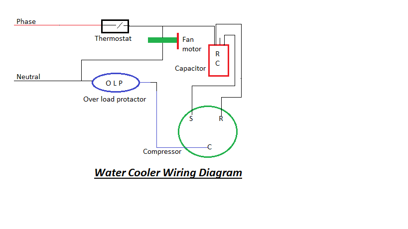
Water Cooler Wiring Diagram Wiring Diagram And Schematics

Wiring Diagram Of Refrigerator And Water Cooler Wiring diagram of refrigerator and water cooler. figure 4 16 liquid cooling system block diagram. schematic diagram of the cooling water circuit scientific. fresh water sea cooling system for marine sel engine. evaporative cooler annotated schematic diagram of png image transpa free on seekpng. modified water coolers sourav s sen. Gather the necessary tools and materials. before starting the wiring process, make sure you have all the required tools and materials. this includes a screwdriver, wire strippers, electrical tape, wire nuts, and the evap cooler wiring diagram provided by the manufacturer. 2. turn off the power.

The Ultimate Guide To Understanding The Wiring Diagram Of A Water Cooler Proper installation and wiring are essential for the optimal functioning of the evaporative cooler. the wiring diagram of an evaporative cooler includes various components that work together to ensure efficient cooling. these components include a motor, pump, thermostat, and junction box. the motor powers the fan, while the pump circulates. An evaporative cooler switch wiring diagram is a schematic that shows the various connections and components of a switch used in an evaporative cooler. this diagram helps electricians and technicians understand how the switch should be wired and connected to the cooler’s motor and power source. 3 pin and 4 pin fan wire diagrams. 3 pin fan connections. *cable coloring varies from fan to fan. pin name. color. color. color. color. 1. The wiring diagram will indicate which wire should be connected to the corresponding terminal. two speed motors: two speed motors offer more flexibility for controlling the speed of the evaporative cooler. these motors typically have three wires, labeled “high,” “medium,” and “low.”. the “high” wire is used for the highest speed.
Water Cooler Wiring Diagrams 3 pin and 4 pin fan wire diagrams. 3 pin fan connections. *cable coloring varies from fan to fan. pin name. color. color. color. color. 1. The wiring diagram will indicate which wire should be connected to the corresponding terminal. two speed motors: two speed motors offer more flexibility for controlling the speed of the evaporative cooler. these motors typically have three wires, labeled “high,” “medium,” and “low.”. the “high” wire is used for the highest speed. In the air water, and cooler wiring diagram all motor connections are shown with a capacitor. the two way switches are used to colour all three motors. the fan motor has two speeds, low and high, controlled from the first switch. the second switch controls the swing motor. the 3rd switch controlled the water pump motor. air room cooler wiring. : wiring diagrams manufacturer reserves the right to change, at any time, specifications and designs without notice and without obligations. 5 a200061 fig. 5 – heaters kfceh3201f20b kfceh3301c20b a190008 fig. 6 – heater kfceh1601315b notes: legend 85 yel blk plug 2 heat strip 4 relay 1 1Ø schematic diagram field power wiring gnd.

Water Cooler Wiring Diagram Water Cooler Wiring Waterођ In the air water, and cooler wiring diagram all motor connections are shown with a capacitor. the two way switches are used to colour all three motors. the fan motor has two speeds, low and high, controlled from the first switch. the second switch controls the swing motor. the 3rd switch controlled the water pump motor. air room cooler wiring. : wiring diagrams manufacturer reserves the right to change, at any time, specifications and designs without notice and without obligations. 5 a200061 fig. 5 – heaters kfceh3201f20b kfceh3301c20b a190008 fig. 6 – heater kfceh1601315b notes: legend 85 yel blk plug 2 heat strip 4 relay 1 1Ø schematic diagram field power wiring gnd.

Comments are closed.