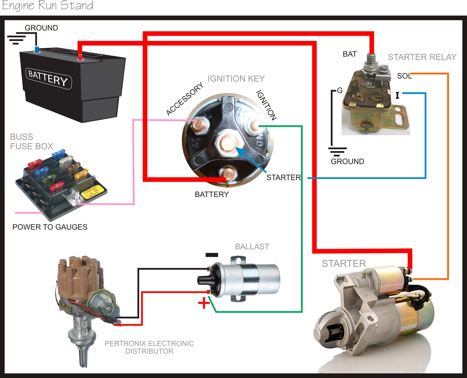
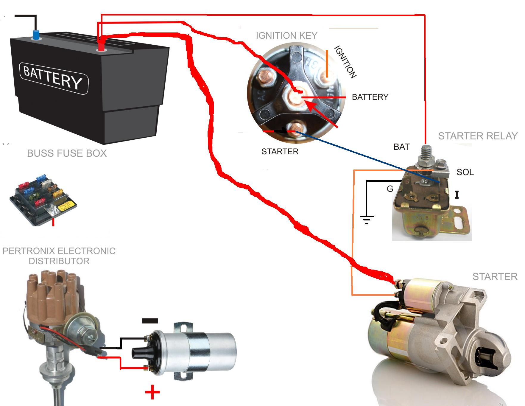
Wiring Diagram Engine Stand

Engine Stand Diagram Kill switch goes in the coil wire. unless you want to do this repeatedly for test and tune. all you really need is a set of jumper cables and a coil wire. hook up jumper cables to starter and block and a wire to the coil. use a screwdriver to start by jumping the main and s terminal. disconnect jumper cable to kill it. Diy engine run stand plans. this is a complete set of plans to build this engine stand. this is for plans only – no materials, parts, or engines included. the plans include all dimensions, instructions, a list of materials required, illustrations, helpful pictures, and wiring diagrams. “24 pages of plans and instructions.

Help Wiring A Engine Run Stand Please Easy Diagram Moparts Forums Clearly indicate the connections between different components using appropriate wiring symbols or labels. show the routing of wires and cables, including any junctions, connectors, and terminal blocks. 6. grounding: highlight the grounding points and connections to ensure proper grounding of the engine run stand. Two engine mount posts are required. drill the 1⁄2” diameter through holes in the top of the post before cutting the bevel on the end. after cutting the bevel on the end, use a flat file to remove burrs from the holes on the inside of the tubes. cut the 1⁄2” steel pipe to fit snugly inside of the tube. 1) battery cable from on battery to big post on starter. 2) battery cable from on battery to engine block, and test stand. 3) 10 ga, wire from back of alt. to battery. 4) plug on alt. 2 wires, 1 goes back to the back of alt, other goes to battery but add a 47 50 ohm resistor in line the wire before battery. Run the wire from the i terminal on the solenoid directly to the terminal on the coil, or run it to the terminal on the ballast resistor "outlet" side. when the solenoid is energized, there should be battery voltage present on the i terminal. i hope that makes sense. rmonty, mar 25, 2018. share post #9.

How To Wire Up Engine Test Stand 1) battery cable from on battery to big post on starter. 2) battery cable from on battery to engine block, and test stand. 3) 10 ga, wire from back of alt. to battery. 4) plug on alt. 2 wires, 1 goes back to the back of alt, other goes to battery but add a 47 50 ohm resistor in line the wire before battery. Run the wire from the i terminal on the solenoid directly to the terminal on the coil, or run it to the terminal on the ballast resistor "outlet" side. when the solenoid is energized, there should be battery voltage present on the i terminal. i hope that makes sense. rmonty, mar 25, 2018. share post #9. I start engines on engine stands with just a few wires . a ground cable from a battery on the ground to the engine block a positive cable to the starter top post a remote starter button hooked to the starter solenoid and a 10 or 12 gauge wire with a switch in the middle plugged into the bat connection on the hei and the other at. Re: wiring diagram for engine on stand. by bbodie52 » wed feb 13, 2019 6:54 am. the engine serial number is your first clue as to the actual nature of the engine. this number is located to the right of the generator alternator, between the top sheet metal shroud and the oil filter adapter casting. the suffix letters can provide a clue.

Comments are closed.