Wiring Diagram For Ceiling Fan With 2 Switches

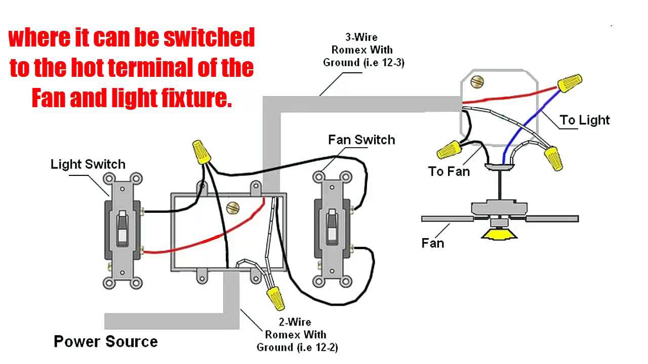
Wiring A Ceiling Fan And Light To 2 Switches In practical we have to connect the terminals of the capacitor to the red and blue wire of the fan. after connecting the capacitor the red wire and the neutral black wire from the fan will be connected to the source and neutral through the switch. fig 2: schematic diagram of the internal circuit of a ceiling fan. The wiring diagram for a ceiling fan with 2 switches typically involves two hot wires, a neutral wire, and a ground wire. the two hot wires are used to control the fan and the light separately. one hot wire is connected to the fan switch, while the other hot wire is connected to the light switch. the neutral wire is connected to the white wire.

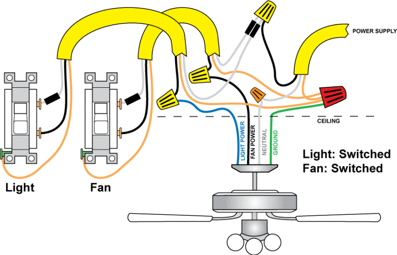
Wiring Diagram Of A Fan In your setup, the white wire in the 3 would get black markings on both ends. so would the white wire between the switches. the upper switch's red pigtail also needs a black marking; it is always hot. in the 3 cable, mark black on both ends as blue. in the 2 cable between the switches, the black wire gets tagged with red tape on both ends. Step 2: unpack fan and prep for install. link to my fan: baxtan 56″ ceiling fan (i’ve also used this hack with this, larger fan: honeywell ceiling fans xerxes, 62 inch) feed the electrical wires from the motor, through the downrod and then screw the downrod into the threads on the top of the motor. threading the wire can be a bit tricky if. 1. gather the necessary tools and materials. before starting the wiring process, gather all the necessary tools and materials, including a voltage tester, wire connectors, electrical tape, a screwdriver, and the wiring diagram provided by the manufacturer. 2. turn off the power supply. This wiring diagram illustrates the connections for a ceiling fan and light with two switches, a speed controller for the fan and a dimmer for the lights. use this arrangement when the source is at the switches. here the input of each controller is spliced to the black source wire with a wire nut. from there, 3 wire cable runs to the ceiling.

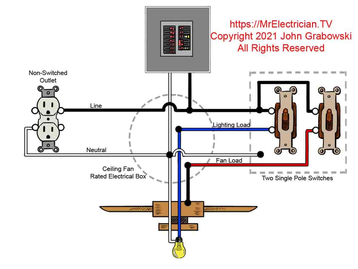
Ceiling Fan Wiring Diagram 2 Switches 1. gather the necessary tools and materials. before starting the wiring process, gather all the necessary tools and materials, including a voltage tester, wire connectors, electrical tape, a screwdriver, and the wiring diagram provided by the manufacturer. 2. turn off the power supply. This wiring diagram illustrates the connections for a ceiling fan and light with two switches, a speed controller for the fan and a dimmer for the lights. use this arrangement when the source is at the switches. here the input of each controller is spliced to the black source wire with a wire nut. from there, 3 wire cable runs to the ceiling. The fan control switch usually connects to the black wire and the light kit switch to the red wire of a 3 way cable. in this diagram, the black wire of the ceiling fan is for the fan, and the blue wire is for the light kit. ground connection diagram is shown separately. ceiling fan switch wiring diagram using two 2 wire nm’s. 4. switching the light and fan from separate switches (two switches) this is the most versatile way to electrically wire a ceiling fan with a light kit. it allows for separate control over both the fan and the light in the room. there are also lots of really convenient switches that put this dual control into one neat little package.

Comments are closed.